OnAir 2000 Digital Mixing Console
Date printed: 20.11.03 Section 2
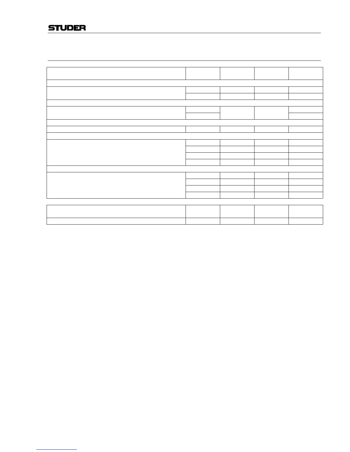
CONTENTS PART FOUR – DIAGRAMS FADER SECTION
Input Modules
Assembly
No.
Diagram
Component
Layout
Parts List
Block Diagram Mic Input Module
Mic Input Module 1.942.220.23 .22 .22 .23
Insert Send 1.942.221.00 .00 .00 .00
Block Diagram Line Input Module
Line Input Module with Transformer 1.942.230.22 1.942.230.22
Line Input Module no Transformer 1.942.232.22
1.942.230.21 1.942.230.21
1.942.232.22
Block Diagram Digital Input Module
Digital Input Module 1.942.240.23 .23 .21 .23
Block Diagram Analog Hex Input Module
Analog Hex. Input Module 1.942.245.22 - .22 -
Analog Hex. Input 1.942.246.00 .00 .00 .00
Hex. Input Controller 1.942.252.81 .81 .81 .81
Connection Board 39 Pol 1.942.247.00 .00 .00 .00
Block Diagram Digital Hex Input Module
Digital Hex. Input Module 1.942.250.22 - .22 -
Digital Hex. Input 1.942.251.81 .81 .81 .81
Hex. Input Controller (see Analog Hex. Input Module above) 1.942.252.81 .81 .81 .81
Connection Board 39 Pol (see Analog Hex. Input Module above) 1.942.247.00 .00 .00 .00
Surface
Assembly
No.
Diagram
Component
Layout
Parts List
Channel Front Board 1.942.210.22 .21 .20 .22
 Loading...


