GTS Technical Manual
9. April 2021 Edition: V1.00/2021 5-34
Copyright © 2020, Diversey
05.30.23 tool lowering unit - tool lowering unit - 3500µicro_V1.00.fm
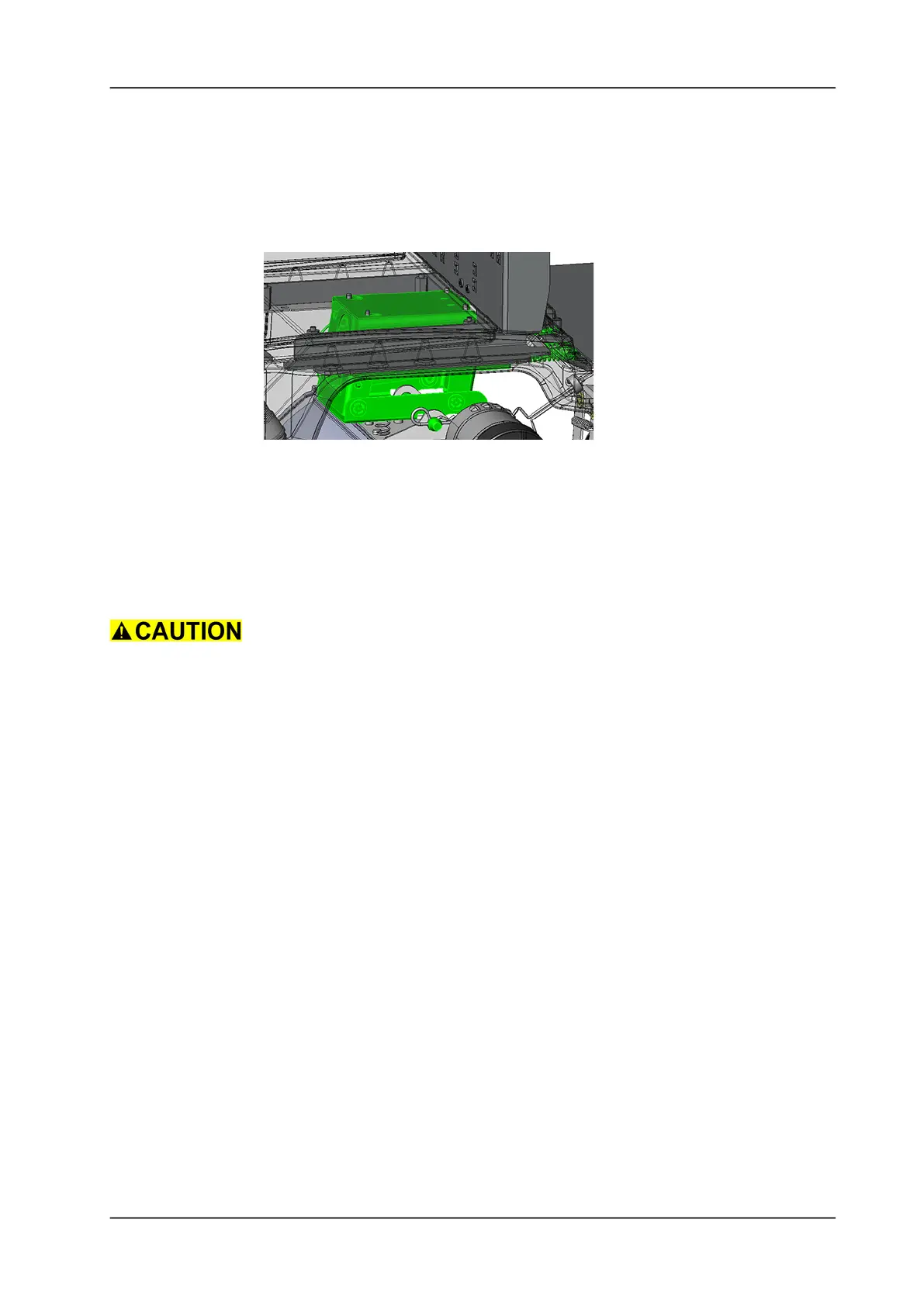
• Thread in the cable of linear drive through the whole in the
chassis.
• Position and engage the three support screws on the tool
lowering unit in the corresponding mounting slots in the chassis
(refer to screw No.2 in picture: Tool lowering unit details).
• Move the tool lowering unit to the front side to the mounting
position.
Picture 50: Tool lowering unit position
• Mount the fixation screw of the tool lowering unit (refer to screw
No.1 in picture: Tool lowering unit details).
• Tighten all 4 screws of the tool lowering unit.
• Thread in the ending of the metal rope trough the castor wheel.
• Place the metal rope holder which is located on the tool lowering
offset and mount the retaining washer.
Make sure that the metal rope and cable of the linear drive do not
interfere with the movement of the tool lowering unit.
• Place new cable ties to fixated and secure all the cables.
• Connect the cable of the linear drive to the electronics.
• Mount the brush drive according to chapter MOUNTING OF
BRUSH DRIVE.
• Mount the seat cover according to chapter MOUNTING OF SEAT
COVER.