Sening® is a registered trademark of FMC Technologies
MN F09 002 US DOK-383E Issue/Rev. 3.65 (02/24)
MultiFlow Configuration of the MultiFlow
Status of the allocated ext. output should assume
inverted status of the reference in/output.
Up to 5 project dependencies can be defined. (0, 10 ..
39)
Use output to control an additional hose path.
Designation of the additional hose path
ATTENTION:
The settings for a local (internal) CAN Bus cannot
be altered until further notice.
Node number of the main board on the internal CAN
Bus.
Node number of the first display on the internal CAN
Bus.
Node number of the second display on the internal
CAN Bus.
Changes on the CAN Bus parameters will take effect after restarting the
system.
9.3.1.14.1
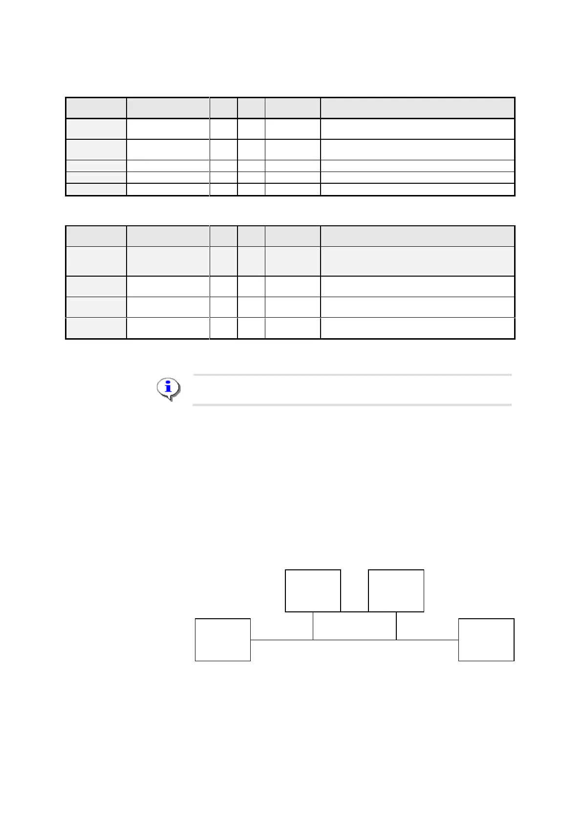
Notes on the CAN Bus Connection
The CAN Bus enables the connection of additional devices (e.g. other
MultiFlows or a TMC truck management computer) to the devices using
the CAN Bus for communicating between one another.
In order to ensure trouble-free communications on the CAN Bus, the CAN
Bus must be “terminated”. This means that termination resistances must
be set electronically at both ends of the line.
Device 2
without
termination
Device 3
without
termination
Device 1
with
termination
Device 4
with
termination
Termination CAN Bus
Parameter 3.1.6.2 “CAN bus termination” tells a MultiFlow whether the
termination is to be activated (1 = “Yes”) or not (0 = “No”). Put differently: