The "Alarm event" parameter of the respective sensor must be set for
the sensor monitoring.
The monitoring ID is a consecutive number. It is set to zero only after a
reset (versions 5.01 and earlier: menu 4.4, versions 5.02 and later:
menu 4.4.1).
The GPS position can only be given when the MultiFlow is operating
with a GPS-compatible EMIS.
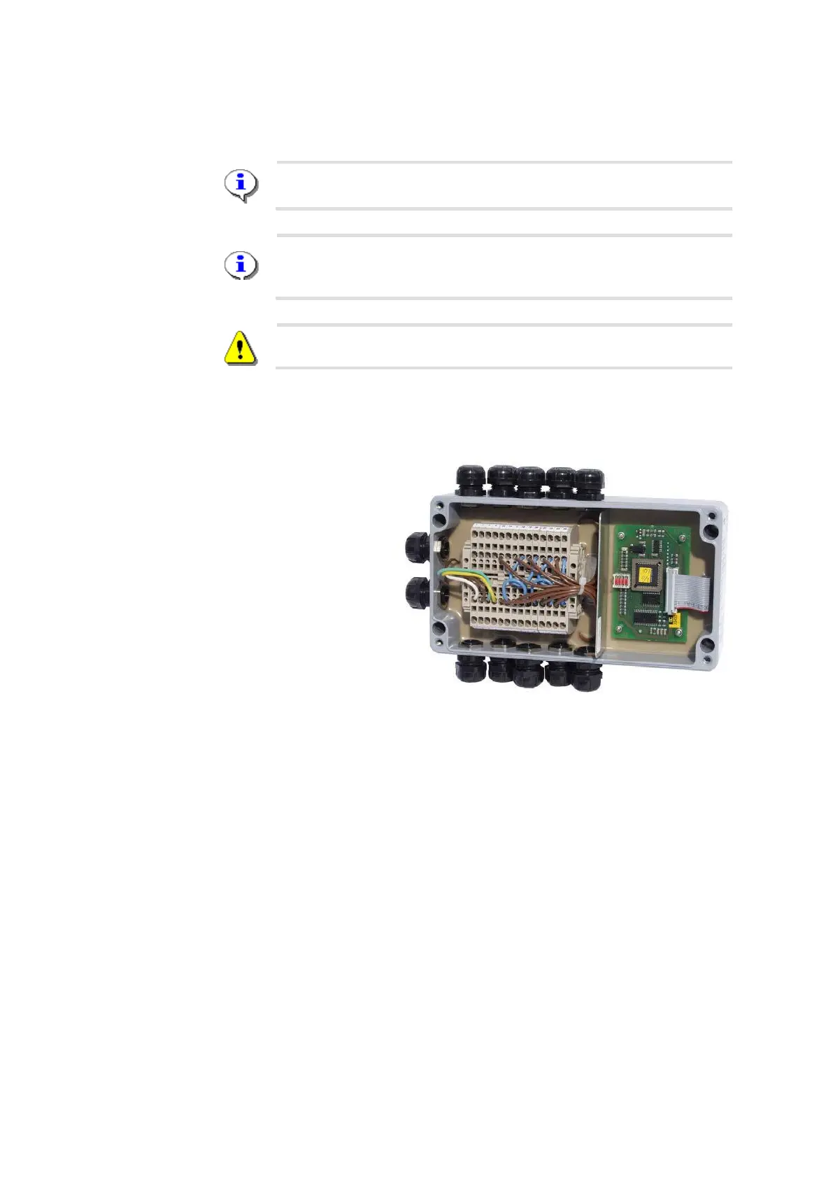
9.14 IO Interface - MFIO2
Parts no.: MFIO2
Drawing no.: 51.352180 / S. 352
Circuit diagram no: 51.352197 / S. 353
Fig. 4 : IO interface – MFIO2
The connection of the IO interface to the MultiFlow allows the use of an
additional 8 outputs and 2 inputs. The IO interface is connected to the
MultiFlow via the external CAN bus.
The connection of the IO interface enables users to generate specific in-
and output links. Additional hose paths can also be defined via the freely
configurable outputs.
9.14.1 IO Interface Functional Description - MFIO2
The IO interface can be configured from each MultiFlow. It is configured
according to the specifications directly after the MultiFlow turn-on and is
then ready for operation. The user is notified about the respective
connection status of the IO module in the event section of the start
screen.