Lab 5 – Interrupts
Run Code to Verify Interrupts are Enabled
13. Click Run … the program should stop at your first breakpoint.
14. Open the Registers window in CCS (or show it, if it’s already open).
If the Registers window isn’t open, do so by:
View → Registers
15. Verify Port1 bits: DIR, OUT, REN, IE, IFG.
The first breakpoint (should have) halted the processor right before setting the GIE bit. We’ll
look at that in a minute; for now, we want to view the GPIO Port 1 settings. Scroll/expand the
registers to verify:
• P1DIR.0 = 1 (pin in output direction)
• P1DIR.1 = 0 (input direction – to be used for generating an interrupt)
• P1REN.1 = 1 (we enabled the resistor for our input pin)
• P1OUT.0 = 0 (we set it low to turn off LED)
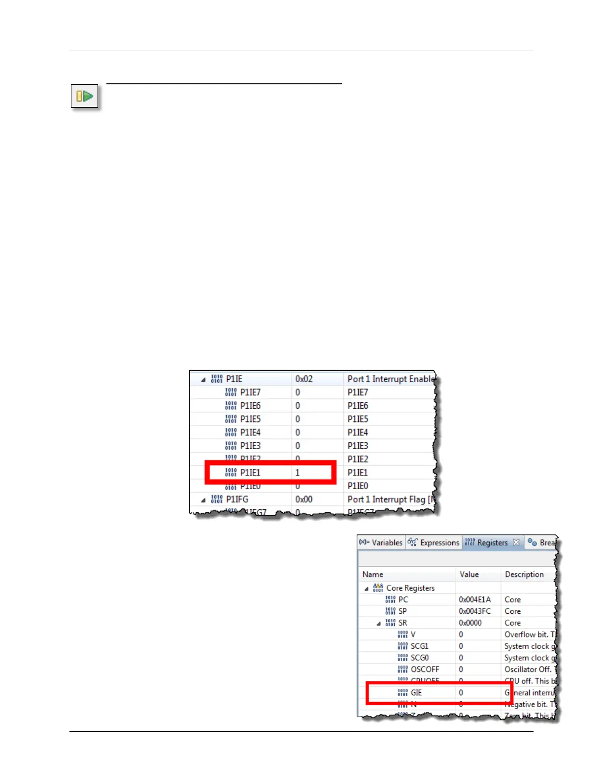
• P1IE.1 = 1 (our button interrupt is enabled)
• P1IFG.1 = 0 (at this point, we shouldn’t have received an
interrupt – unless you already pushed the button…)
Here’s a snapshot of the P1IE register as an example …
16. Next, let’s look at the Status Register (SR).
You can find it under the Core Registers at the top
of the Registers window.
You should notice that the GIE bit equals 0, since
we haven’t executed the line of code enabling
interrupts globally, yet.
5 - 46 MSP430 Workshop - Interrupts