Timer Basics: How Timers Work
Timer Summary – showing multiple CCR’s
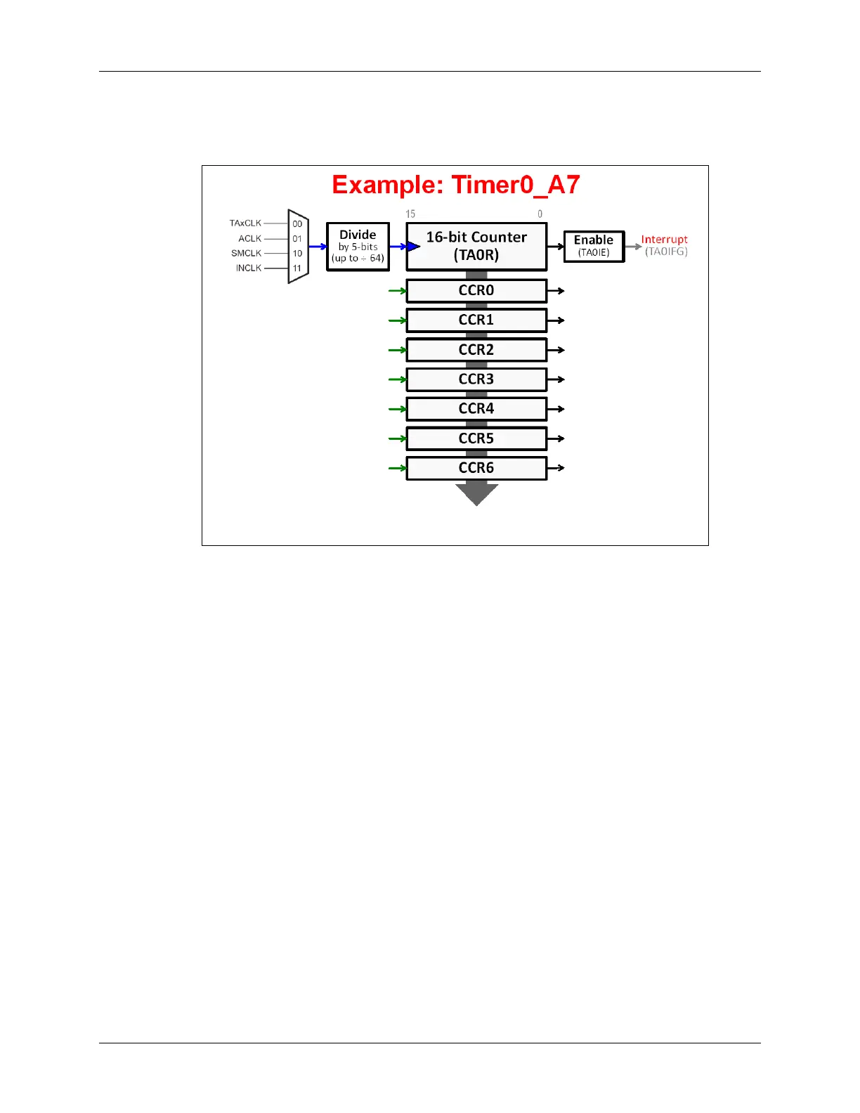
The following example of a Timer0_A7 provides us a way to summarize the timer’s hardware.
Remember:
• Timer0 means it’s the first instance of Timer_A on the device.
• _A7 means that it’s a Timer_A device and has 7 capture/compare registers (CCR’s)
• The clock input, in this example, can be driven by a TACLK signal/pin, ACLK, SMCLK or
another internal clock called INCLK.
• The clock input can be further divided down by a 5-bit scalar.
• The TA0IE interrupt enable can be used to allow (or prevent) an interrupt (TA0IFG) from
reaching the CPU whenever the counter (TA0R) rolls over.
6 - 10 MSP430 Workshop - Timers