Timer Basics: How Timers Work
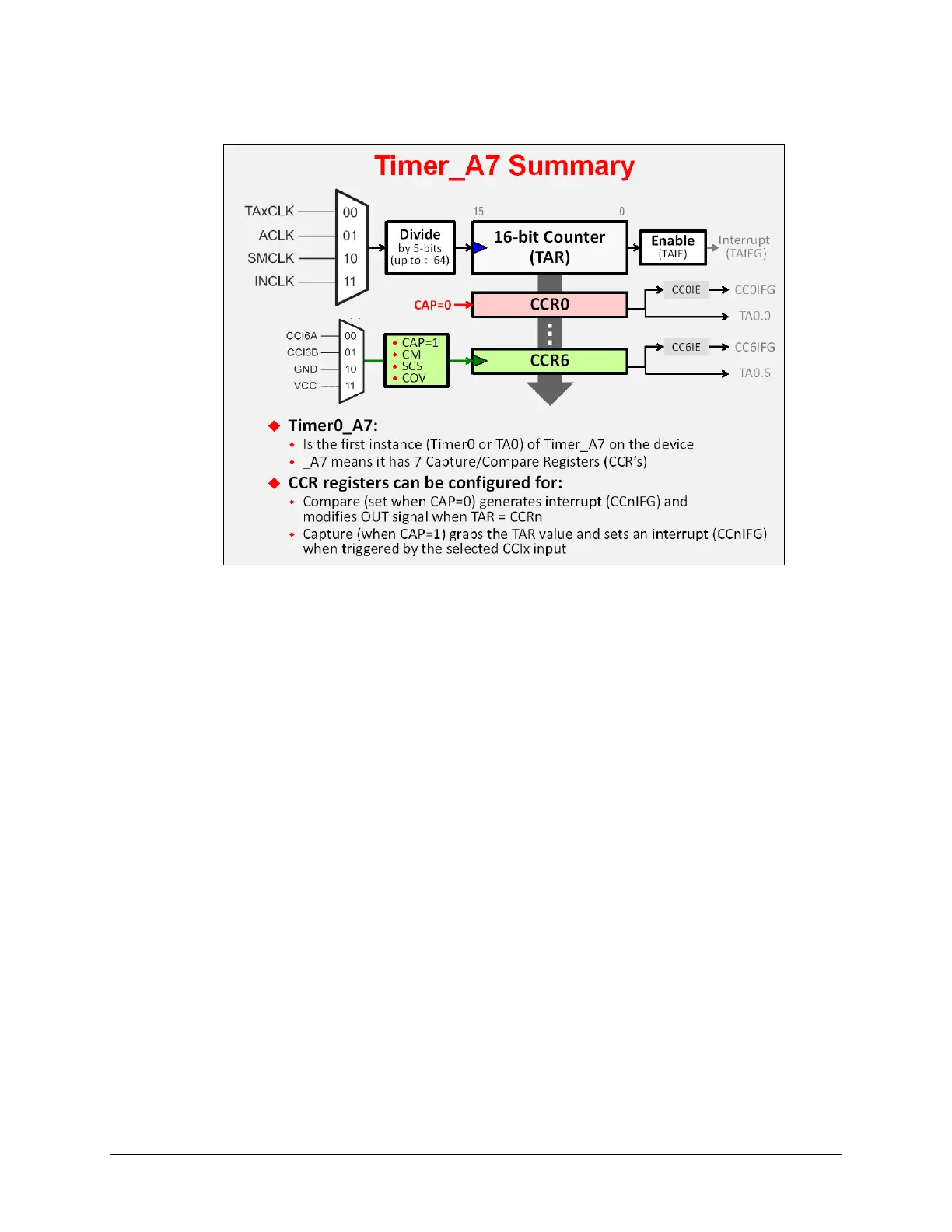
This next diagram allows us to look more closely at the Capture and Compare functions.
Every CCR register has its own control register. Notice above, that the “CAP” bit configures
whether the CCR will be used in capture (CAP=1) or compare mode (CAP=0).
You can also see that each CCR has an interrupt flag, enable, and output signal associated with
it. The output signal can be routed to a pin or a number of other internal peripherals.
As we go through the rest of this chapter, we’ll examine further details of the CCR registers as
well as the various “actions” that the timer generates.
In the next section, we’ll begin examining how to configure the timer using the MSP430ware
DriverLib API.
MSP430 Workshop - Timers 6 - 11