4-58 4181383 First Edition
ELECTRICAL
4
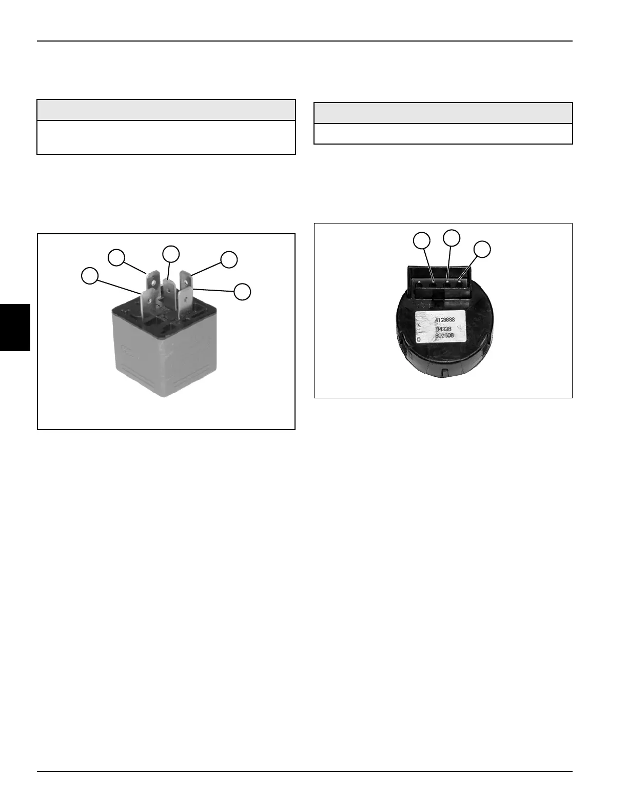
Glow Plug Relay
See Figure 4-24.
1. Park the mower safely. (See “Park Mower Safely” on
page 1-5.)
2. Remove the glow plug relay. (See “Glow Plug Relay”
on page 4-70.)
Figure 4-24
3. Connect one test lead to terminal (4).
4. Connect the other test lead to terminal (1) and check
for continuity.
Is continuity indicated?
YES Proceed to step 5.
NO The relay is faulty; replace the relay.
5. Connect one test lead to terminal (4).
6. Connect the other test lead to terminal (3).
7. Connect a 12-volt DC power source to terminals
(2 and 5).
8. Check for continuity across terminals (3 and 4).
Is continuity indicated?
YES The relay is good.
NO The relay is faulty; replace the relay.
Key Switch Test
See Figure 4-25.
1. Park the mower safely. (See “Park Mower Safely” on
page 1-5.)
2. Remove the key switch from the instrument panel.
(See “Key Switch” on page 4-71.)
Figure 4-25
3. Move key switch to the ON position.
4. Check continuity between terminals (2 and 3).
Is continuity indicated?
YES Proceed to step 5.
NO The key switch is faulty.
5. Move the key switch to the START position. Check
continuity between terminals (1, 2, and 3).
Is continuity indicated?
YES The key switch is good.
NO The key switch is faulty; replace the switch.
6. Install key switch.
NO
Required Tools or Equipment
Digital Multimeter, or Ohmmeter, or Continuity Tester
12-Volt DC Power Source and Leads
4
2
5
3
1
TN1531
Required Tools or Equipment
Digital Multimeter, Ohmmeter, or Continuity Tester
TN0676
1
2
3
 Loading...


