ELECTRICAL
4181383 First Edition 4-71
4
Instrument Panel
Removal and Installation
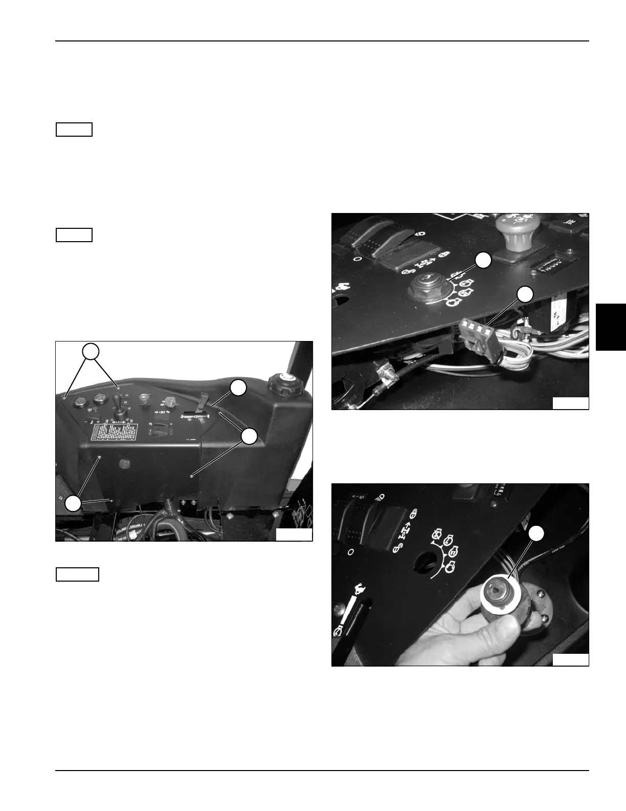
See Figure .
NOTE
If servicing individual components, it is not necessary to
completely remove the instrument panel. In these cases,
the instrument panel can be moved aside for access to
components.
1. Park the mower safely. (See “Park Mower Safely” on
page 1-5.)
NOTE
Label all wires before disconnecting to ensure correct
installation.
2. Disconnect the negative (–) battery cable at the
battery.
3. If removing the instrument panel, disconnect the
positive (+) battery cables from the battery.
Figure 4-56
NOTES
• Seat removed for photo clarity.
• If moving the instrument panel aside, use caution to
prevent stretching or kinking of the cables.
4. Remove six screws (1) and move the panel (2) aside,
or service components as needed.
Installation Notes
• Anti-Seize must be applied to screw threads when
installing instrument panel.
• Install the instrument panel by reversing the order of
removal.
Key Switch
Removal and Installation
See Figures 4-57 and 4-58.
1. Park the mower safely. (See “Park Mower Safely” on
page 1-5.)
2. Disconnect the negative (–) battery cable at the
battery.
3. Remove instrument panel. (See “Instrument Panel”
on page 4-71.)
Figure 4-57
4. Disconnect the key switch wiring harness (1).
5. Remove retaining nut (2) from the key switch
assembly.
Figure 4-58
6. Remove key switch assembly (3) from bottom of the
instrument panel.
Installation Note
Install the key switch by reversing the order of removal.
TN1459
1
2
1
1
2
1
TN1606
3
TN1607
 Loading...


