4-74 4181383 First Edition
ELECTRICAL
4
5. Remove park brake proximity switch (6).
Installation Note
Install the park brake proximity switch by reversing the
order of removal.
Raise/Lower Switch
Removal and Installation
See Figures 4-66 and 4-67.
1. Park the mower safely. (See “Park Mower Safely” on
page 1-5.)
2. Disconnect the negative (–) battery cable at the
battery.
3. Remove the instrument panel. (See “Instrument
Panel” on page 4-71.)
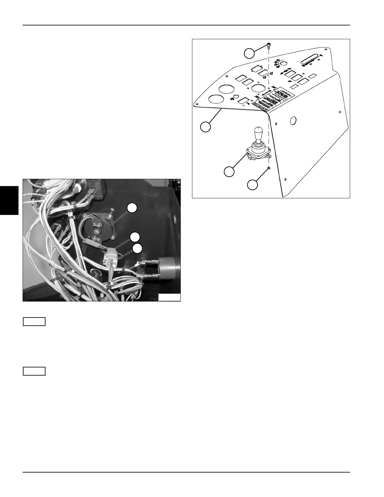
Figure 4-66
NOTE
Label all wiring connectors and record orientation of the
joystick before removing to ensure correct installation.
4. Disconnect the joystick wiring connector (1) from the
wiring harness (2).
NOTE
When removed, the joystick may come out as two
separate pieces. If the joystick is to be tested after
removal, connect the two pieces using the mounting
hardware.
Figure 4-67
5. Remove four nuts (3) and screws (4), and remove
joystick (5) from instrument panel (6).
Installation Note
Install the joystick by reversing the order of removal.
Seat Switch
Removal and Installation
The seat switch removal and installation is included in the
seat and mount plate removal and installation procedure.
(See “Seat and Mount Plate” on page 9-10.)
Neutral Proximity Switch
Removal and Installation
See Figures 4-68 and 4-69.
1. Park the mower safely. (See “Park Mower Safely” on
page 1-5.)
2. Disconnect the negative (–) battery cable at the
battery.
TN1485
1
5
2
TN1479
4
3
5
6
 Loading...


