ELECTRICAL
4181383 First Edition 4-65
4
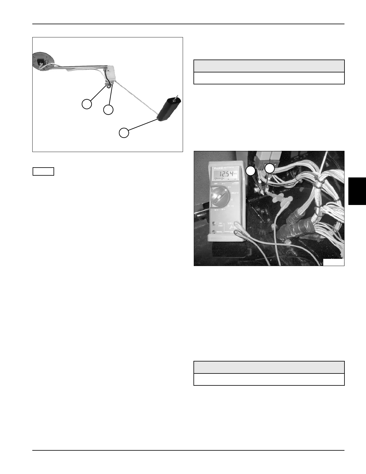
Figure 4-38
NOTE
Float shown in the empty position.
3. Connect the test leads to terminals (1 and 2).
4. Set the meter to read ohms.
5. Move the float (3) to the empty position and read the
resistance value.
Is the resistance value between 211 and 286
ohms?
YES Proceed to step 6.
NO The sensor is faulty; replace fuel level
sensor.
6. Move the float (3) to the full position and read the
resistance value.
Is the resistance value between 26 and 35 ohms?
YES The sensor is good.
NO The sensor is faulty; replace fuel level
sensor.
Circuit Breaker Test
See Figure 4-39.
1. Park the mower safely. (See “Park Mower Safely” on
page 1-5.)
2. Allow engine to cool completely.
3. Set the multimeter to 20 volts DC.
4. Connect the black test lead to the negative
(–) battery terminal.
Figure 4-39
5. Connect the red test lead to each of the circuit
breaker terminals (1 and 2).
Is battery voltage indicated?
YES Circuit breaker is good.
NO Circuit breaker is faulty; replace circuit
breaker.
Fuel Pump Test
See Figures 4-40 and 4-41
1. Park the mower safely. (See “Park Mower Safely” on
page 1-5.)
2. Allow engine to cool completely.
2
1
3
TN1591
Required Tools or Equipment
Digital Multimeter, Ohmmeter, or Continuity Tester
Required Tools or Equipment
Digital Multimeter, Ohmmeter, or Continuity Tester
2
1
TN1614
 Loading...


