9-12 4181383 First Edition
ACCESSORIES AND MISCELLANEOUS REPAIR
9
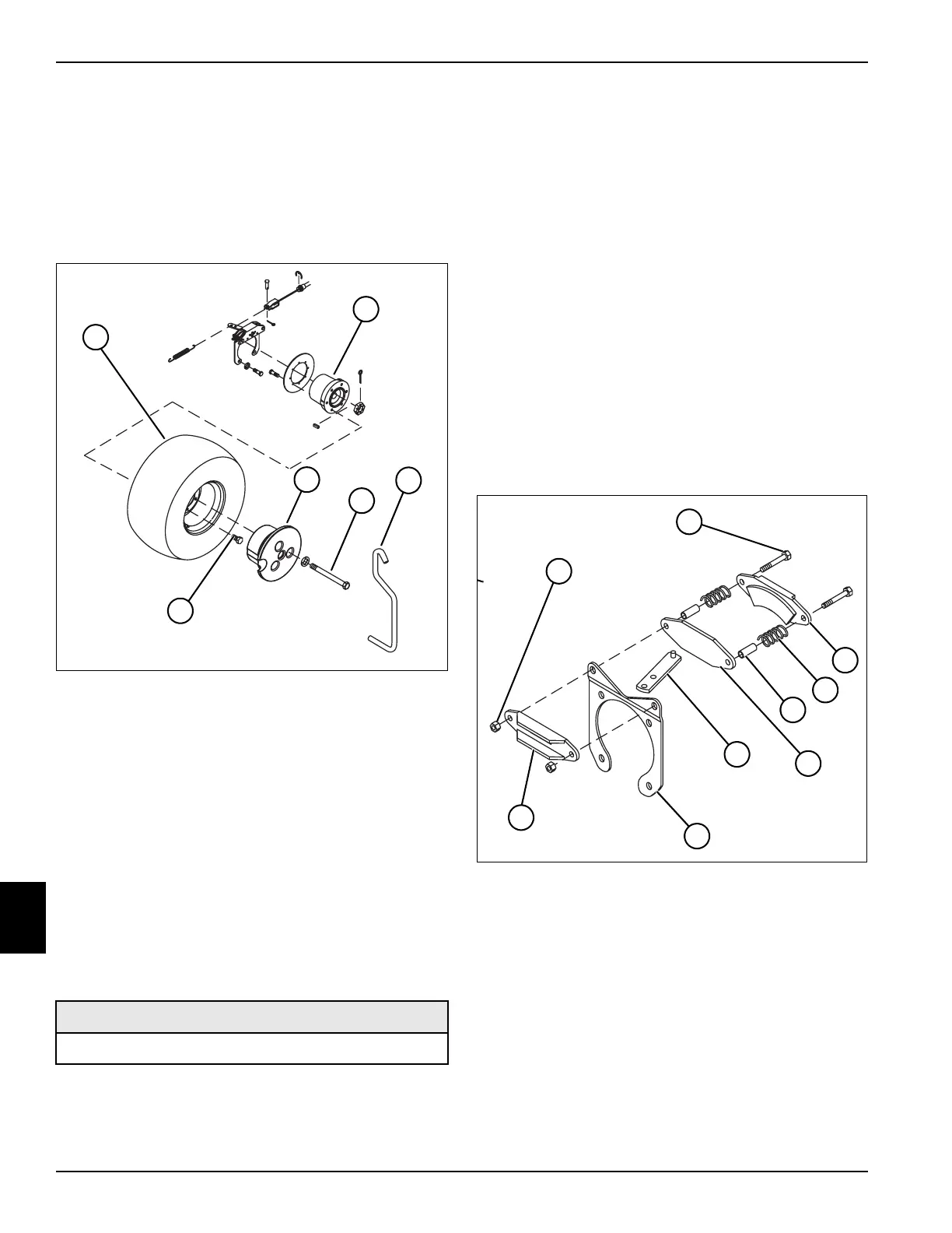
Front Wheels
Removal and Installation
See Figure 9-17.
1. Park mower safely. (See “Park Mower Safely” on
page 1-5.)
2. Remove key from keyswitch.
Figure 9-17
3. Insert wheel weight tool (3) in center of weight (5).
Remove three hex bolts (4) holding weight (5) to
wheel (1).
4. Using wheel weight tool (3), carefully lift weight (5)
from wheel (1) and set aside.
5. Block both sides of rear wheels using suitable wheel
blocks.
6. Loosen, but do not remove, wheel-to-hub lug bolts
(6).
7. Raise and support front of mower until wheels are off
the ground.
8. Remove wheel-to-hub lug bolts (6). Remove wheel
(1) and inspect tread area for tears or other damage.
Replace tire if damage is excessive.
Installation Notes
• Inspect and clean any rust from hub (5) or wheel
mounting area. Apply Anti-Seize compound to lug
bolts.
• Install wheel by reversing the order of removal.
• Torque wheel-to-hub lug bolts to 85—95 lb-ft. (115—
128 N·m).
• Set tire pressure to 16 psi (110) kPa).
Brake Unit
Disassembly, Inspection, and Assembly
See Figure 9-18.
1. Park mower safely. (See “Park Mower Safely” on
page 1-5.)
2. Remove key from key switch.
3. Remove front wheels. (See “Front Wheels” on
page 9-12.)
Figure 9-18
4. Remove all tension from brake cables. (See “Brake
Pedal/Linkage Adjustment” on page 9-4.)
5. Remove brake cable and return spring from cam
lever (7).
6. Remove two brake assembly mounting hex bolts (2)
and nuts (1), from brake support (9).
7. Inspect two guide bushings (5) and springs (4) for
rust, damage, or excessive wear. Replace if
damaged or worn.
8. Remove cam lever (7) and check pivot pin for rust or
wear. Clean or replace if rusted or damaged.
Required Materials
Anti-Seize Compound
T
N
1
5
4
2
6
1
2
4
3
5
T
N
1
5
4
5
9
1
2
4
5
8
3
6
7
 Loading...


