4-48 4181383 First Edition
ELECTRICAL
4
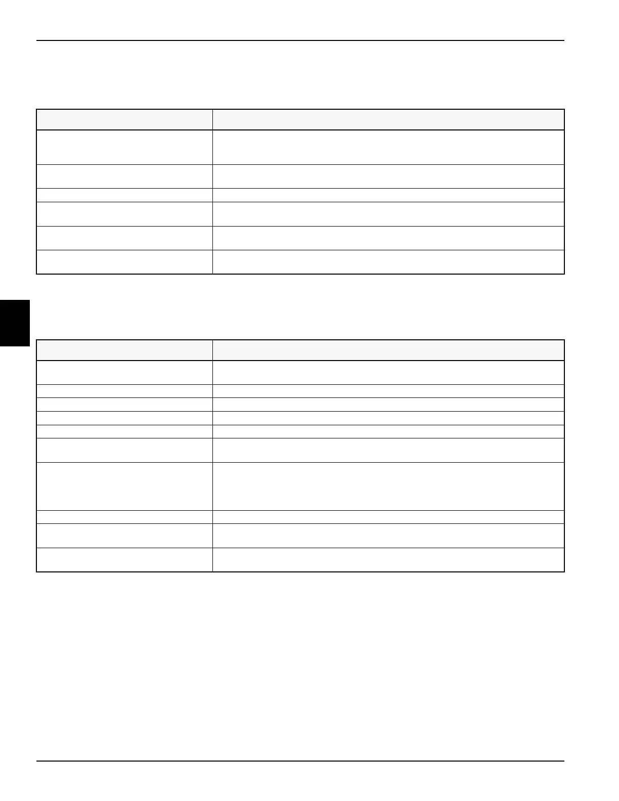
Glow Plug Circuit
Symptom: Glow plugs do not get hot.
Start Circuit
Symptom: Starter motor solenoid does not engage.
Probable Cause Remedy
Faulty control module output circuit. Cycle key switch between the run and start positions and check control module glow plug
relay output LED. If the LED does not come on, substitute the control module with a
known good control module.
Faulty power circuit. Check continuity between 50A thermal circuit breaker F3 and glow plug relay terminal 30.
Continuity must be indicated.
Faulty glow plug relay. Test relay. (See “Relay Tests” on page 4-57.)
Open glow plug relay ground circuit. Check continuity between glow plug relay terminal 85 and ground. Continuity must be
indicated.
Faulty glow plug relay output circuit. Measure voltage between glow plug terminal strip and ground. Voltage must be
approximately 12 VDC.
Faulty connection at glow plug terminal
strip.
Clean and tighten ring terminal connector.
Probable Cause Remedy
Park brake pedal is in the released
position.
Place the park brake pedal in the locked position.
Traction pedal not in the neutral position. Move the traction pedal to the neutral position.
Mow switch is in the mow position. Place the mow switch in the off position.
Faulty park brake proximity switch. Test switch. (See “Park Brake Circuit” on page 4-46.)
Faulty neutral proximity switch. Test switch. (See “Neutral Circuit” on page 4-46.)
Faulty key switch. With the key switch in the start position, check control module start sw input LED. If the
LED does not light, test switch. (See “Key Switch Test” on page 4-58.)
Faulty control module output. With the key switch in the start position, check control module starter relay output LED.
If the LED does not come on, substitute the control module with a known good control
module.
Note: The glow plug circuit must time out before the starter relay output becomes active.
Faulty Start relay. Test relay. (See “Relay Tests” on page 4-57.)
Faulty power circuit. Measure voltage between start relay terminal 30 and ground. Voltage must be
approximately 12 VDC.
Faulty start relay ground circuit. Measure continuity between start relay terminal 85 and ground. Continuity must be
indicated.
 Loading...


