4-50 4181383 First Edition
ELECTRICAL
4
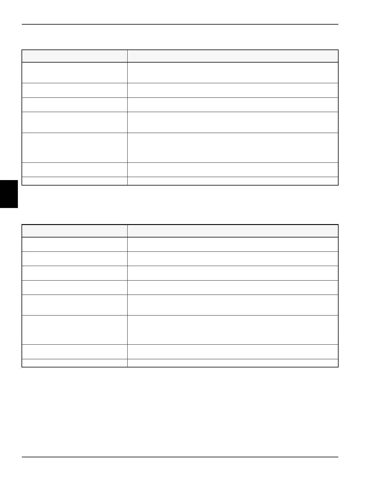
Symptom: Raise solenoid does not energize.
Mow Circuit
Symptom: Mow solenoid does not energize.
Probable Cause Remedy
Faulty raise/lower switch. With the raise/lower switch in the lower position, check control module joystick raise sw
LED. If the LED does not light, test the switch. (See “Raise/Lower Switch Test” on
page 4-59.)
Faulty switched power circuit. Measure voltage between raise/lower switch org/pnk terminals and ground. Voltage must
be approximately 12 VDC.
Faulty raise switch input circuit. With the raise/lower switch in the raise position, measure voltage between control module
joystick raise sw input terminal and ground. Voltage must be approximately 12 VDC.
Faulty control module output circuit With the raise/lower switch in the raise position, check control module lift sol output LED.
If the LED does not light, substitute the control module with a known good control
module.
Faulty raise solenoid output circuit. Momentarily place the raise/lower switch in the raise position.
Measure voltage between control module raise solenoid output terminal and ground.
Measure voltage between raise solenoid tan/blu wire terminal and ground.
Voltage must be approximately 12 VDC.
Open raise solenoid ground circuit. Check continuity between lower solenoid blk wire terminal and ground. Continuity must
be indicated.
Faulty raise solenoid. Test solenoid. (See “Solenoid Test” on page 4-63.)
Probable Cause Remedy
Raise/lower switch was not momentarily
placed in the lower position.
Momentarily place the raise/lower switch in the lower position to activate the cutting units.
Faulty mow switch. With the mow switch in the on position, check control module mow sw input LED. If the
LED does not light, test switch. (See “Mow Switch” on page 4-62.)
Faulty switched power circuit. Measure voltage between mow switch org/pnk terminal and ground. Voltage must be
approximately 12 VDC.
Faulty control module input circuit. With the mow switch in the mow position, measure voltage between control module mow
switch input terminal and ground. Voltage must be approximately 12 VDC.
Faulty control module output circuit With the raise/lower switch in the raise position, check control module lift sol output LED.
If the LED does not light, substitute the control module with a known good control
module.
Faulty mow solenoid output circuit. With the mow switch in the on position and the raise/lower switch in the lower position,
measure voltage between control module mow solenoid output terminal and ground.
Measure voltage between mow solenoid gry/org wire terminal and ground.
Voltage must be approximately 12 VDC.
Open mow solenoid ground circuit. Check continuity between mow solenoid blk wire terminal and ground. Continuity must be
indicated.
Faulty mow solenoid. Test solenoid. (See “Solenoid Test” on page 4-63.)
 Loading...


