ELECTRICAL
4181383 First Edition 4-79
4
Figure 4-78
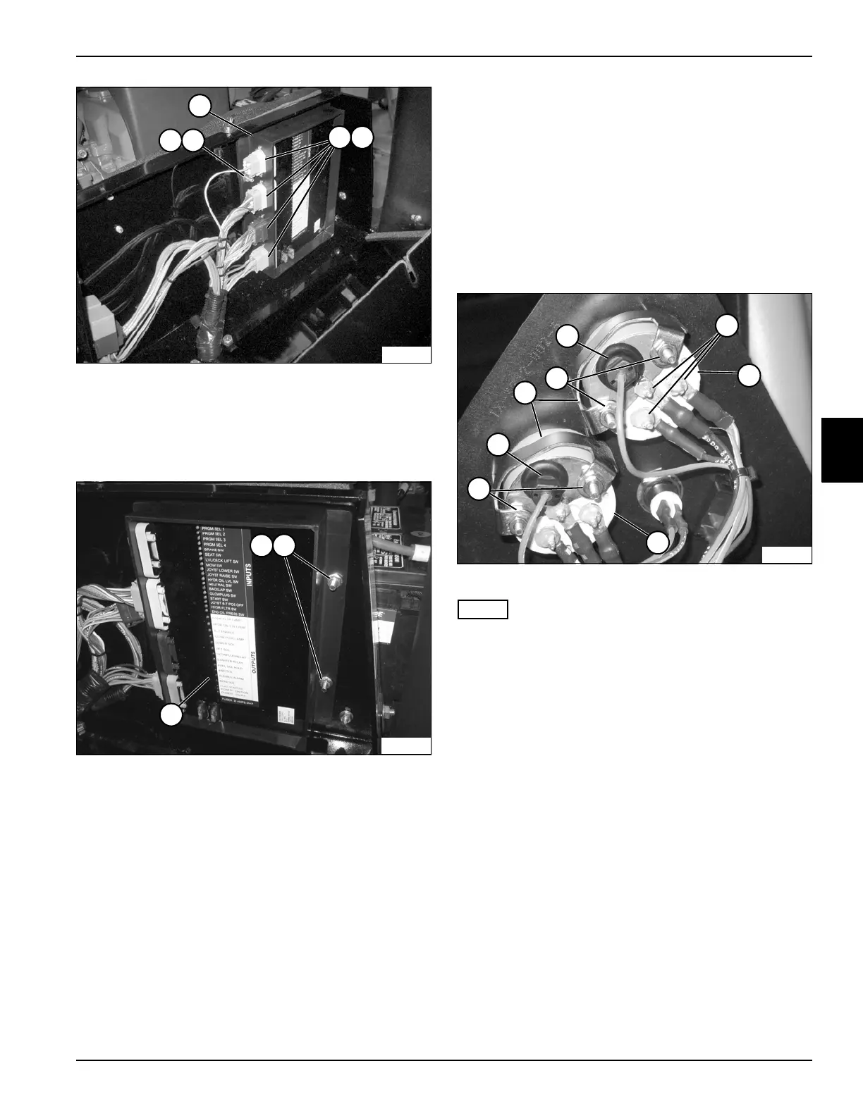
5. Disconnect the wiring harness connectors (3) from
the control module sockets (4).
6. Remove mounting screws and nuts (5 and 6) from
control module (7).
Figure 4-79
7. Remove mounting screws and nuts (5 and 6) from
control module (7).
8. Remove the control module (7).
Installation Notes
• Harness connections to control module only fit one
way. Do not force plug into control module.
• Install the control module by reversing the order of
removal.
Fuel and Water Gauge
Removal and Installation
See Figures 4-80 and 4-81.
1. Park the mower safely. (See “Park Mower Safely” on
page 1-5.)
2. Disconnect the negative (–) battery cable at the
battery.
3. Remove the instrument panel. (See “Instrument
Panel” on page 4-71.)
Figure 4-80
NOTE
Label all wires before disconnecting to ensure correct
installation.
1. Remove three nuts (1), and disconnect the wires
from the fuel gauge (2) and water gauge (3).
2. Remove indicator lights from gauge housing by
pulling gently on the bulb socket (4).
3. Remove the two nuts (5) securing gauge brackets
(6).
TN1464
65
7
3 4
TN1465
5 6
7
TN1612
1
3
2
4
4
5
6
5
 Loading...


