8-16 4181383 First Edition
CUTTING UNITS
8
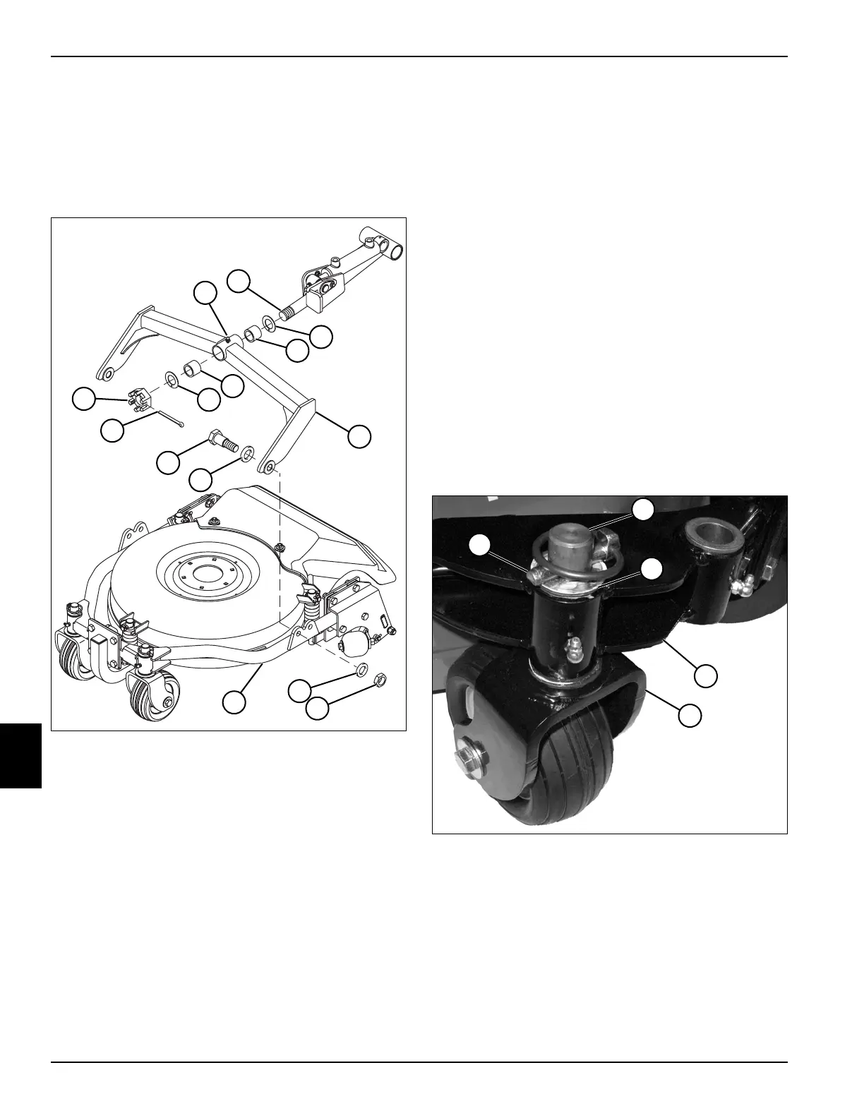
Rear Deck Yoke
Removal and Installation
See Figure 8-7.
1. Park the mower safely. (See “Park Mower Safely” on
page 1-5.)
Figure 8-7
2. Remove cotter pin (11), slotted hex nut (12), and
plastic washer (3) from lift arm pivot shaft (2).
3. Inspect lift arm shaft bushings (4). Remove only if
replacement is required.
4. Roll the cutting unit forward until the deck yoke (5)
clears the lift arm pivot shaft (2). Retain lift arm shaft
bushings (4) inside deck yoke (5).
5. Remove lock nut (7), washers (6 and 9), and screw
(10) from both sides of the deck frame (8) and deck
yoke (5).
6. Remove yoke (5) from deck frame (8).
Installation Notes
• Install the rear deck yoke by reversing the order of
removal.
• Apply grease on lift arm pivot shaft bushings (4) and
lift arm pivot shaft (2) before installation. (Refer to
“Safety, Operation, and Maintenance Manual” for
grease specifications.)
• After assembly, apply grease to grease fitting (1).
(Refer to “Safety, Operation, and Maintenance
Manual” for grease specifications.)
Deck Caster Wheels
Removal and Installation
See Figures 8-8 through 8-10.
1. Park the mower safely. (See “Park Mower Safely” on
page 1-5.)
2. Raise and support cutting deck approximately 6
inches above ground to allow room to remove caster
from deck frame.
3. Stop engine, set park brake, and remove ignition key.
Figure 8-8
4. Support caster wheel assembly (5).
5. Remove lock pin (1) and flat washer (3) from caster
yoke shaft (2).
6. Remove caster from bottom of deck frame (4).
TN1414
11
7
6
3
4
1
4
3
9
10
12
2
5
8
TN1421
1
3
4
5
2
 Loading...


