ELECTRICAL
4181383 First Edition 4-63
4
3. With the ignition key turned to the ON position, use a
multimeter to check for battery voltage at the
orange/pink wire (1).
4. Battery voltage should be available at terminal (1). If
not, check the wiring harness for loose, broken, or
dirty connections.
5. Remove the wire connectors from the switch
terminals.
6. Remove the mow switch from the control panel.
Figure 4-34
7. Place test leads on switch terminals (1 and 2).
8. Place the switch in the ON (pulled up) position.
9. Check for continuity.
Is continuity indicated?
YES The switch is good.
NO The switch is faulty; replace the switch.
10. Place the switch in the OFF (push down) position.
Is continuity indicated?
YES The switch is faulty; replace the switch.
NO The switch is good.
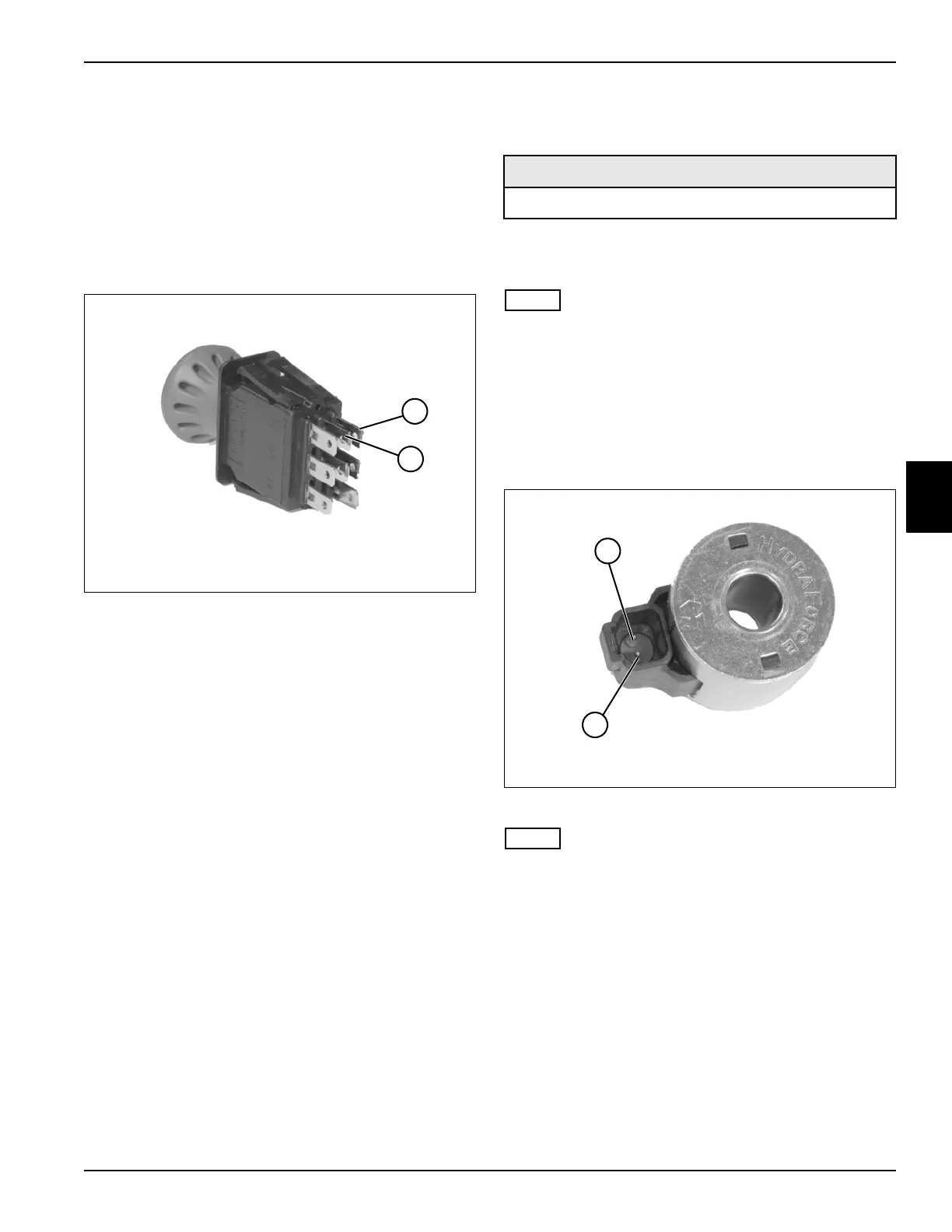
Solenoid Test
See Figure 4-35.
1. Park the mower safely. (See “Park Mower Safely” on
page 1-5.)
NOTE
This procedure applies to the following solenoid coils:
• Mow Solenoid
• Raise Solenoid
• Lower Solenoid
2. Locate the component solenoid to be tested.
Remove the solenoid coil from the machine. (See
“Solenoid Coils” on page 4-75.)
Figure 4-35
NOTE
On some meters it will be necessary to select a range for
the solenoid being tested.
3. Using a multimeter or ohmmeter, measure the ohms
resistance between terminals (1 and 2). Refer to the
specifications listed for the specific solenoid voltage.
• Raise Solenoid Coil—7.0 ohms ± 10% at 68°F
• Lower Solenoid Coil—6.0 ohms ± 10% at 68°F
• Mow Solenoid Coil—9.8 ohms ± 10% at 68°F
Does the resistance through the component
match the specified value listed?
YES The solenoid is good.
NO The solenoid is faulty; replace the solenoid.
TN1589
1
2
Required Tools or Equipment
Digital Multimeter or Ohmmeter
1
2
TN1595
 Loading...


