4-72 4181383 First Edition
ELECTRICAL
4
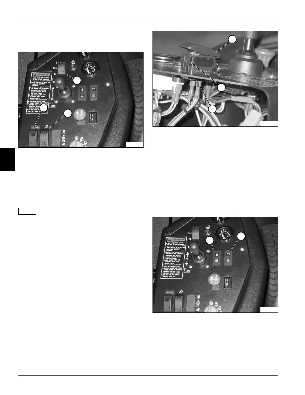
Rocker Switches
See Figure 4-59.
Figure 4-59
This procedure applies to the following switches:
• Traction Control Switch (1)
• Work Light Switch (2)
• Horn Switch (3)
Removal and Installation
See Figure 4-60.
NOTE
Horn switch shown.
1. Park the mower safely. (See “Park Mower Safely” on
page 1-5.)
2. Disconnect the battery negative (–) cable at the
battery.
3. Remove the instrument panel. (See “Instrument
Panel” on page 4-71.)
Figure 4-60
4. Disconnect the switch (4) from the connector wires
(5).
5. Depress tabs (6) on each side of the rocker switch
and lift out of the instrument panel.
Installation Note
Install the rocker switches by reversing the order of
removal.
Indicator Lamps
See Figure 4-61.
Figure 4-61
This procedure applies to the following indicator lamps:
• Engine Preheat/Charge Warning Lamps (1)
• Restricted Hydraulic Filter Warning/Engine
Temperature Warning Lamps (2)
TN1626
2
1
3
4
5
6
TN1608
TN1626
1
2
 Loading...


