4-64 4181383 First Edition
ELECTRICAL
4
Hydraulic Filter Pressure Switch Test
See Figure 4-36.
1. Park the mower safely. (See “Park Mower Safely” on
page 1-5.)
2. Shut down the engine and remove the ignition key.
3. Set the multimeter to the continuity setting.
Figure 4-36
4. Remove the sender wire from the switch.
5. Place one test lead on the switch stud (1).
6. Place the other test lead on the filter head (2).
Is continuity indicated?
YES The switch is faulty; replace the switch.
NO The switch is good.
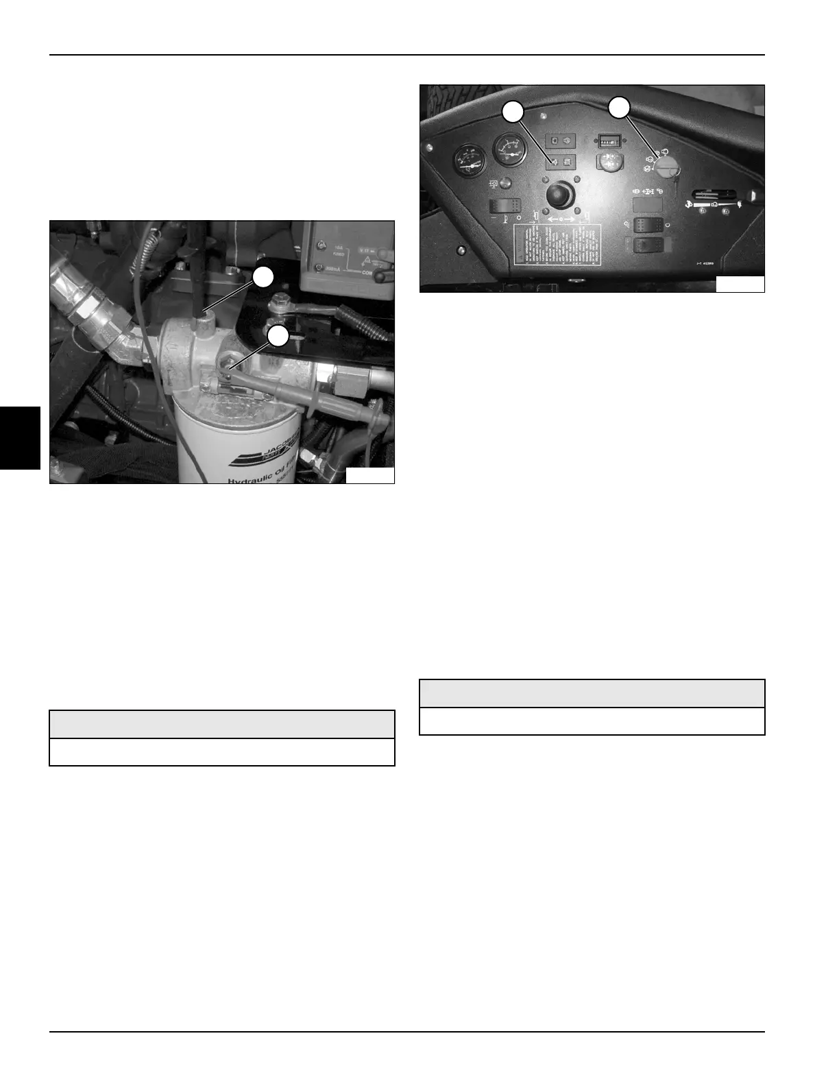
Engine Oil Pressure Switch Test
See Figure 4-37.
1. Park the mower safely. (See “Park Mower Safely” on
page 1-5.)
2. Check the engine oil level. Add oil as needed. (Refer
to “Safety, Operation & Maintenance Manual” for oil
specification.)
Figure 4-37
3. Turn the key switch (2) to the run position.
Does the engine oil pressure warning light (1)
come on?
YES Proceed to step 4.
NO Check the instrumentation Circuit. (See
“Instrumentation Circuit Schematic” on
page 4-40.)
4. Start the engine. (Refer to “Safety, Operation &
Maintenance Manual”.)
Does the engine oil pressure warning light (1) go
out when the engine is running?
YES The warning light is good.
NO Stop the engine immediately and check the
engine. (Refer to the engine manufacturer’s
manual.)
Fuel Level Sensor Test
See Figure 4-38.
1. Park the mower safely. (See “Park Mower Safely” on
page 1-5.)
2. Remove the fuel level sensor from the fuel tank. (See
“Fuel Tank” on page 9-6.)
Required Tools or Equipment
Digital Multimeter, Ohmmeter, or Continuity Tester
TN1590
1
2
Required Tools or Equipment
Digital Multimeter, Ohmmeter, or Continuity Tester
1
2
TN1596
 Loading...


