4-80 4181383 First Edition
ELECTRICAL
4
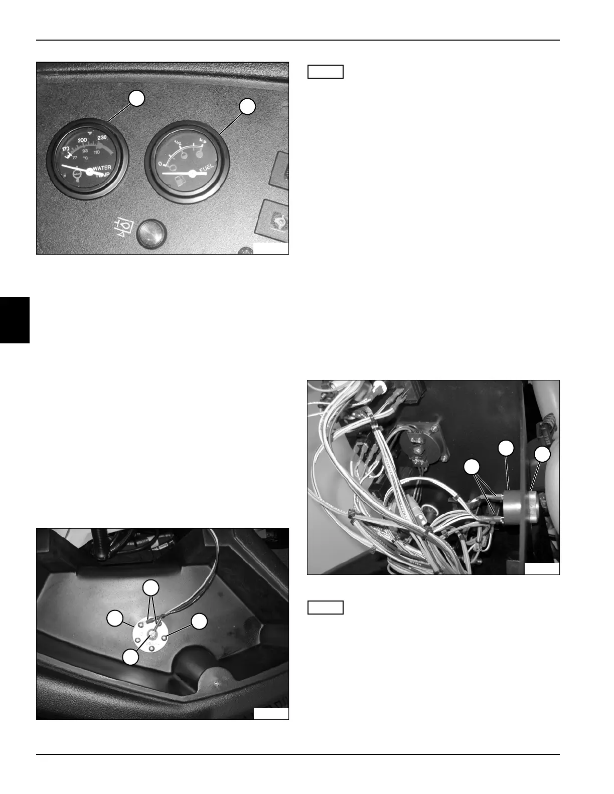
Figure 4-81
4. Lift gauges (2 and 3) straight up and out of the
instrument panel.
Installation Note
Install the fuel and water temperature gauges by
reversing the order of removal.
Fuel Level Sender
Removal and Installation
See Figure 4-82.
1. Park the mower safely. (See “Park Mower Safely” on
page 1-5.)
2. Disconnect the negative (–) battery cable at the
battery.
3. Drain fuel until level is below sender mount opening.
4. Remove the instrument panel. (See “Instrument
Panel” on page 4-71.)
Figure 4-82
NOTE
Label all wires before disconnecting to ensure correct
installation.
5. Remove nut (3), and disconnect wires (1) from fuel
level sender (4).
6. Remove five screws (2).
7. Remove fuel level sender (4).
Installation Note
Install the fuel level sender by reversing the order of
removal.
Horn
Removal and Installation
See Figure 4-83.
1. Park the mower safely.(See “Park Mower Safely” on
page 1-5.)
2. Disconnect the battery negative (–) cable at the
battery.
3. Remove the instrument panel. (See “Instrument
Panel” on page 4-71.)
Figure 4-83
NOTE
Label all wires before disconnecting to ensure correct
installation.
4. Disconnect wires (3) from horn (1).
5. Remove ring (2).
6. Remove horn (1).
Installation Note
Install the horn by reversing the order of removal.
2
3
TN1613
TN1466
3
1
2
4
TN1495
1
2
3
 Loading...


