CUTTING UNITS
4181383 First Edition 8-15
8
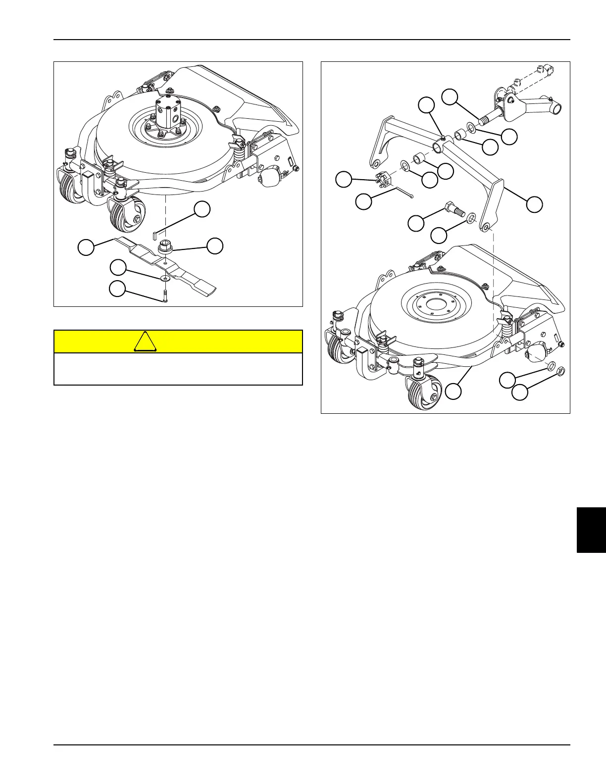
Figure 8-5
!
CAUTION
4. Remove blade screw (4), washer (5), blade (1), blade
adapter (3), and key (2) from hydraulic motor spindle
(not shown).
Installation Notes
• Install blade by reversing the order of removal.
• Tighten blade screw (4) to 75 to 90 lb-ft (100 to 120
N·m).
Front Deck Yoke
Removal and Installation
See Figure 8-6.
1. Park the mower safely. (See “Park Mower Safely” on
page 1-5.)
Figure 8-6
2. Remove cotter pin (11), slotted hex nut (12), and
plastic washer (3) from lift arm pivot shaft (2).
3. Inspect lift arm shaft bushings (4). Remove only if
replacement is required.
4. Roll the cutting unit forward until the deck yoke (5)
clears the lift arm pivot shaft (2). Retain lift arm shaft
bushings (4) inside deck yoke (5).
5. Remove lock nut (7), washers (6 and 9), and screw
(10) from both sides of the deck frame (8) and deck
yoke (5).
6. Remove yoke (5) from deck frame (8).
Installation Notes
• Install the front deck yoke by reversing the order of
removal.
• Apply grease on lift arm pivot shaft bushings (4) and
lift arm pivot shaft (2) before installation. (Refer to
“Safety, Operation, and Maintenance Manual” for
grease specifications.)
• After assembly, apply grease to grease fitting (1).
(Refer to “Safety, Operation, and Maintenance
Manual” for grease specifications.)
Blades are extremely sharp and can cause severe
injury.
TN1408
4
1
5
3
2
TN1411
11
7
6
3
4
1
4
3
9
10
12
2
5
8
 Loading...


