5-18 4181383 First Edition
HYDROSTATIC POWER TRAIN
5
23. Calculate traction system leakage.
(Step 20 – Step 21 / Step 20 x 100 = Leakage
Percentage)
Is traction system leakage 10% or less?
YES The traction system is good. Additional
testing is required. Proceed to “Wheel
Motors Test” on page 5-20.
NO Proceed to next question.
Is traction system leakage 11% to 20%?
YES The traction system is marginal. Additional
testing is required.
NO Proceed to next question.
Is traction system leakage 21% or more?
YES Test individual components in traction
system for leakage.
24. Disconnect and remove test equipment. Install all
hoses and fittings as noted prior to removal.
25. Install and connect all components as noted prior to
test.
26. Check hydraulic oil level. Add oil as needed. (Refer to
“Safety, Operation, and Maintenance Manual” for oil
specifications.)
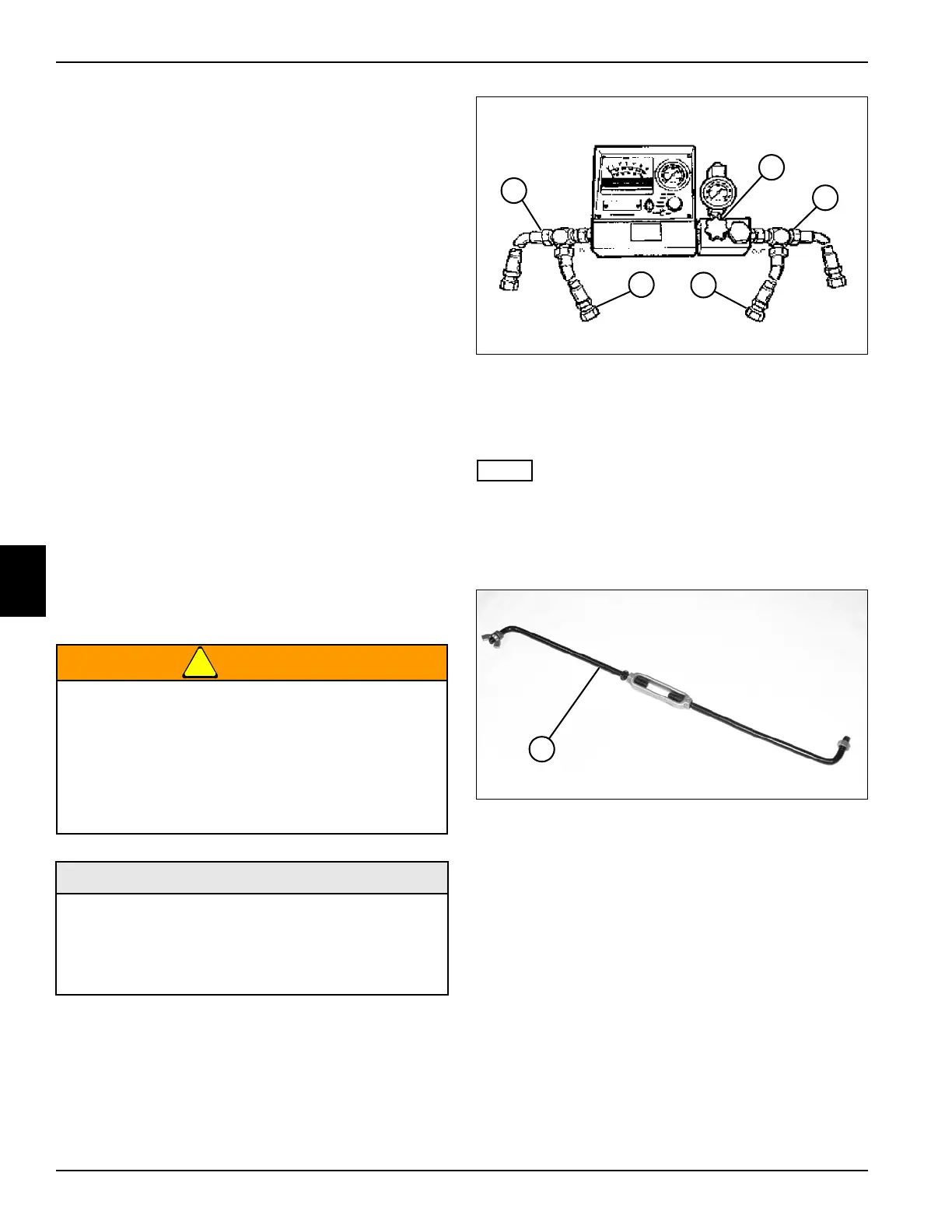
Traction Pump Tests
See Figures 5-16 and 5-17.
!
WARNING
1. Park the mower safely. (See “Park Mower Safely” on
page 1-5.)
2. Before performing this test, perform traction system
test leaving flow meter and flow lock tool connected
as outlined. (See “Traction System Test” on
page 5-16.)
Figure 5-16
3. Install blocking disks at locations (1 and 3).
4. Open flow meter valve (2) completely before starting
engine.
NOTE
Verify engine rpm is within specification (2850 rpm ± 50)
to ensure accurate hydraulic test results.
5. Start engine, release brake, and run at full throttle
(2850 rpm ± 50).
Figure 5-17
6. Adjust flow lock tool (6) to allow pump to produce 15
gpm (57 lpm) in the forward direction.
7. Use the flow meter to warm the hydraulic oil. Turn the
flow meter valve (2) until a reading of 1800 psi (124
bar) or one half of the relief valve rating is reached.
Warm oil to 120—150°F (49—65°C); open valve fully
after operating temperature is reached.
8. After warming the hydraulic oil, verify flow lock tool is
adjusted to allow pump to produce 15 gpm (57 lpm)
in the forward direction.
9. Read and record no load flow.
10. Slowly close flow meter valve (2) until pressure
reaches 2700 psi (186 bar). Read and record loaded
flow.
11. Stop engine, apply brake, and return flow lock tool
back to neutral position.
The hydraulic system is under pressure, and the
oil will be hot.
• Always relieve pressure in the hydraulic
system before performing service.
• Failure to follow appropriate safety
precautions may result in death or serious
injury.
Required Tools and Materials
• Flow Meter
• -12 ORFS Test Hose 4000 psi (276 bar)
• -12 ORFS Blocking Disks
• Flow Lock Tool
5
TN1357
4
2
1
3
6
TN1705
 Loading...


