CUTTING UNITS
4181383 First Edition 8-19
8
8. Remove lock nut (14) and washer (15) from scraper
shaft (13).
9. Remove weldment (10) from roller shaft (11) and
scraper shaft (13).
Installation Notes
• Install the roller by reversing the order of removal.
• Apply grease to fitting.
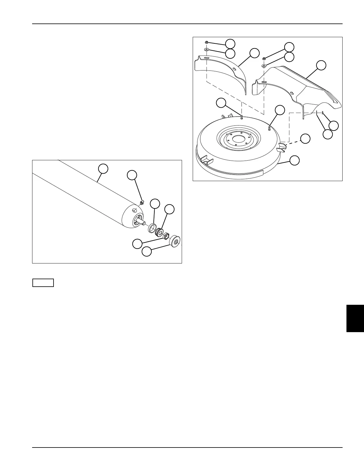
Disassembly, Inspection, and Assembly
See Figure 8-15.
1. Park the mower safely. (See “Park Mower Safely” on
page 1-5.)
2. Remove deck roller from cutting unit. (See “Deck
Roller” on page 8-18.)
Figure 8-15
NOTE
Do not remove bearing cone (3) unless it is necessary to
replace the bearing (4). Always replace the bearing and
bearing cone as a set.
3. Remove seal (5), lock nut (6), and bearing (4) and
bearing cone (3) from both ends of roller (1).
4. Inspect roller, shaft, bearings, and bearing cones for
wear or damage. Replace as necessary.
Assembly Notes
• Assemble the deck roller by reversing the order of
disassembly.
• Apply grease to grease fitting (2) at both ends of
roller (1). (Refer to “Safety, Operation, and
Maintenance Manual” for grease specifications.)
Mower Deck Housing
Disassembly and Assembly
See Figure 8-16.
Figure 8-16
1. Remove nuts (1) and washers (2) from screws (5)
(two for mulch cover, three for rear discharge
deflector).
2. Remove mulch cover (3) or rear discharge deflector
(4) from mower deck (6).
Assembly Note
Assemble the mower deck by reversing the order of
disassembly.
TN1415
1
4
5
3
2
6
TN1409
5
1
2
1
2
5
5
1
2
3
6
4
 Loading...


