HYDRAULICS
4181383 First Edition 6-47
6
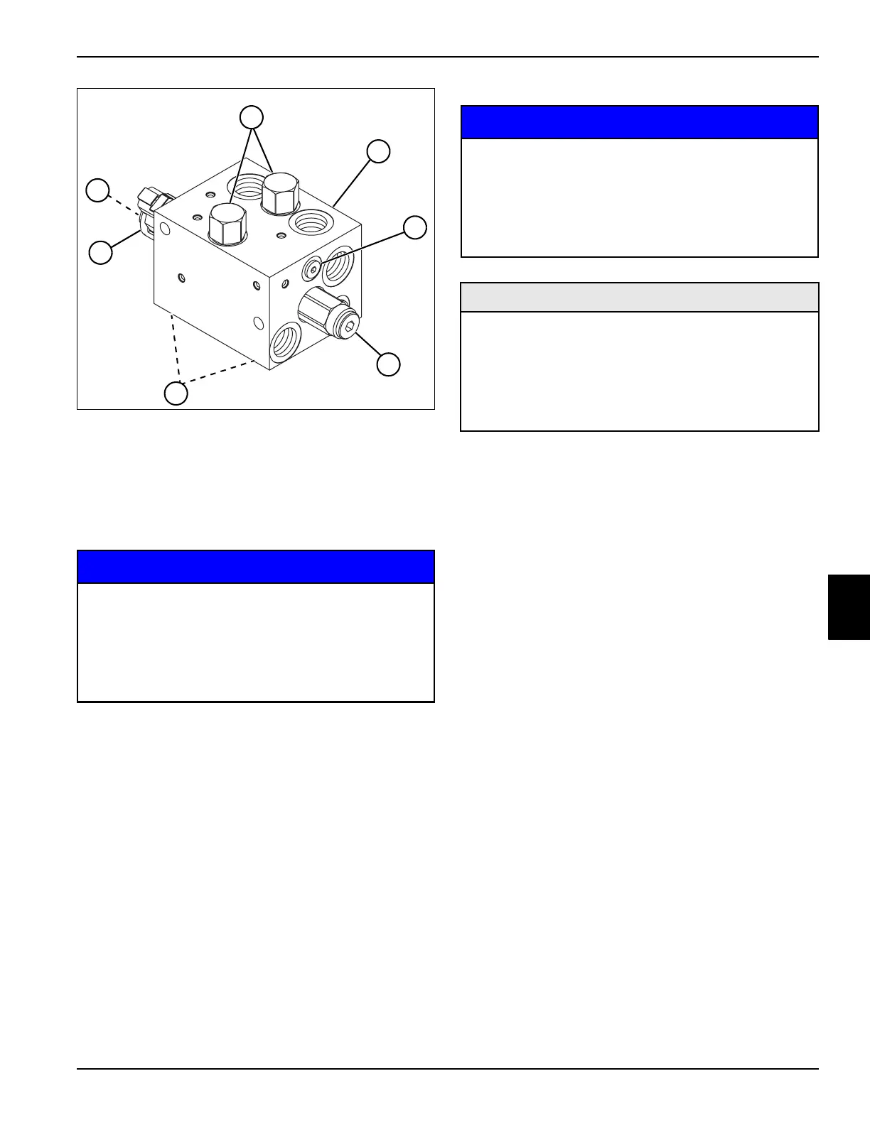
Figure 6-45
NOTICE
2. Clean all parts using clean solvent, and dry using
compressed air.
3. Inspect all parts for wear or damage. Replace parts
as needed.
Assembly Notes
NOTICE
• Assemble the deck valve by reversing the order of
disassembly.
• Lubricate all O-rings prior to assembly.
• Tighten cartridges and relief valve to 25 lb-ft
(34 N·m).
Hydraulic Filter
Removal and Installation
See Figure 6-46.
1. Park the mower safely. (See “Park Mower Safely” on
page 1-5.)
2. Raise engine hood.
3. Drain hydraulic tank.
8 Vented Logic Element Valve (2)
9 Deck Valve Block
10 Load Shuttle Valve
11 Relief Valve
12 Check Valve
13 Mow Solenoid Coil
14 Mow Solenoid Valve
It is important that all component parts are
absolutely clean, as contamination can result in
serious damage and/or improper operation.
Never use shop towels or rags to dry parts after
cleaning, as lint may clog passages. Dry parts
using compressed air.
TN1385
8
12
11
10
9
14
13
It is important that all component parts are
absolutely clean, as contamination can result in
serious damage and/or improper operation.
Never use shop towels or rags to dry parts after
cleaning, as lint may clog passages. Dry parts
using compressed air.
Required Materials
Seal Kit, Vented Logic Element Valve
(Jacobsen P/N 5003579)
Seal Kit, Relief Valve (Jacobsen P/N 5003578)
Seal Kit, Solenoid Valve (Jacobsen P/N 5003578)
Seal Kit, Check Valve (Jacobsen P/N 5003579)
Seal Kit, Load Shuttle Valve (Jacobsen P/N 4134543)
 Loading...


