ELECTRICAL
4181383 First Edition 4-25
4
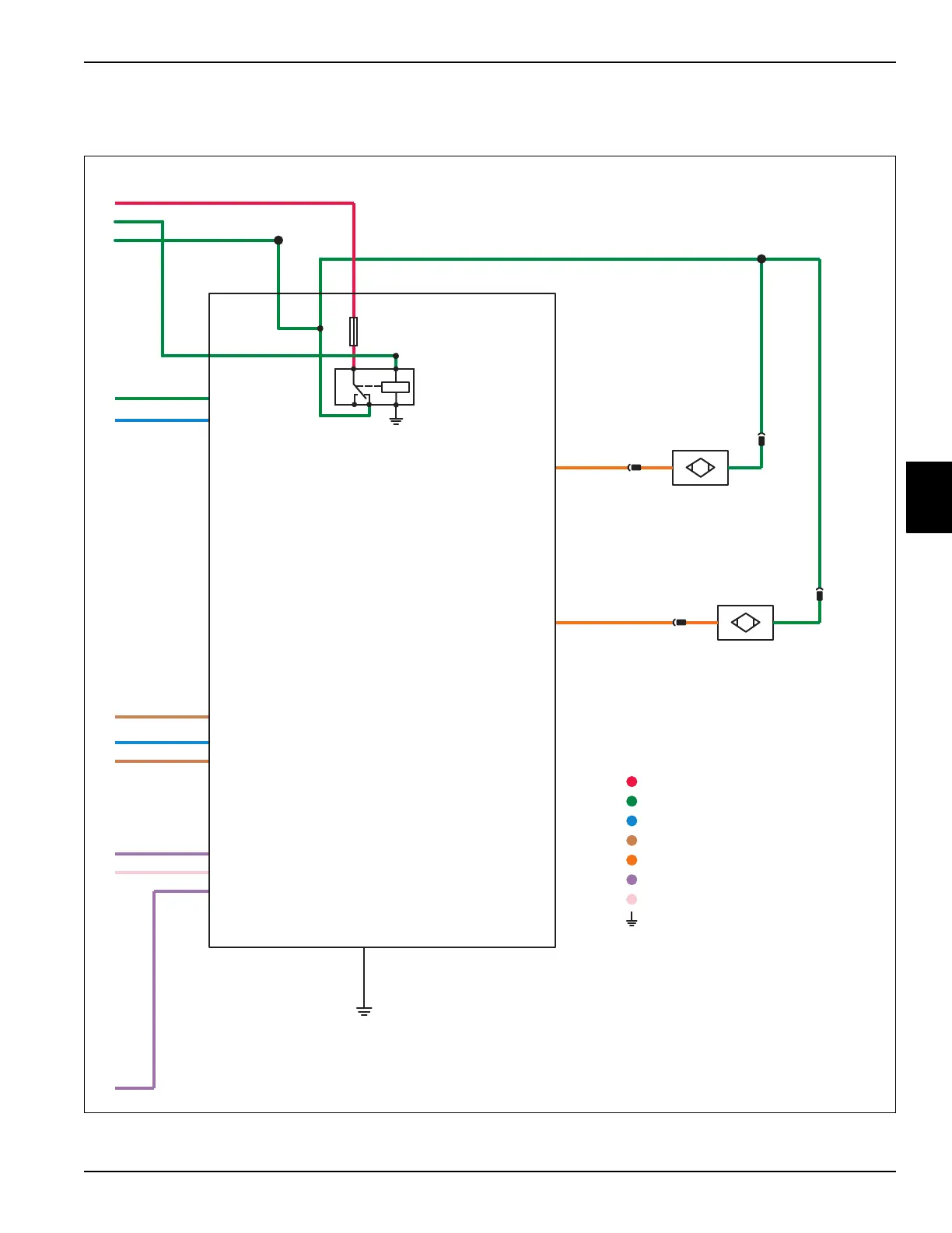
Start and Glow Plug Circuit Schematic
Continued
Figure 4-11
Red Red
Brn/Yel
Org/Yel
Org/Yel J3-2 Switch Power (+)
Org/Wht
Splice 90
Org/
Wht
Org/ Pnk Org/ Pnk Org/ Pnk
Org/
Pnk
8787A 85
8630
Blk
Ground
J3-8
Grn/Yel
Gry/Red
Blu/Wht
Wht
J2-7 Fuel Hold Output (+)
J3-1 Fuel Pull-In Output (+)
J2-6 Glow Plug Relay Output (+)
J2-5 Start Relay Output (+)
F2
20A
Fuse
J3-5 J3-6J3-3
Brn/Yel
J3-12 Fuel Pull-In Input
Pnk/Blu
J1-5 Start Input
Neutral Switch Input J1-2
Park Brake Switch Input J1-7
Org/Yel
J4-2 Select 2 Input
A1
Control
Module
Blk
N.O.
N.O.
2 WhtBrn/Wht
Org/
Pnk
Org/
Pnk
1
S4
Neutral
Proximity
Switch
Brn/Red
S5
Park
Brake
Proximity
Switch
Blk2 Wht
1
Tan/Blk
J2-11 Glow Plug Light Output (-)
Interlock Circuit
Fuel Pull-In Circuit
Fuel Hold-In Circuit
Switched Power Circuit
Unswitched Power Circuit
Start Circuit
Glow Plug Circuit
Ground Circuit
Splice 100
TN1646
 Loading...


