Chapter 1 ’Overview’ — Chassis Description
Amethyst III DTV Smart Switch 33
User Manual
Rear Panel
Amethyst III provides connectors at the rear panel.
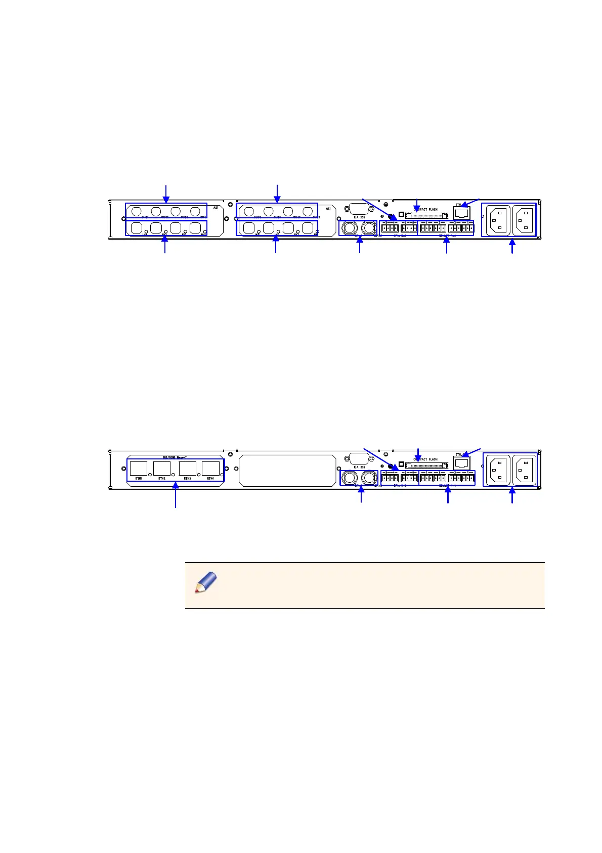
Figure 1-22. Rear panel of ASI Amethyst III equipped with two ASI boards
ASI outputs 1 to 4
Free voltage
contacts
Compact
Flash drive
Ethernet
supervision port
ASI outputs 5 to 8
ASI inputs 1 to 4
ASI inputs 5 to 8
GPI inputs
1 & 2
GPI inputs
3 to 6
Power supply
connectors
PSU1PSU2
The ASI chassis may include one or two ASI boards (1 board = 4 inputs +
4 outputs).
ASI outputs 1, 3, 5 and 7 are smart-secured: a bypass allows having a
signal ev
en when the equipment is off.
Figure 1-23. Rear panel of IP Amethyst III equipped with one Gigabit Ethernet board
Ethernet inputs 1 to 4
Free voltage
contacts
Compact
Flash drive
Ethernet
supervision port
GPI inputs
1 & 2
GPI inputs
3 to 6
Power supply
connectors
PSU1PSU2
Hybrid configuration (i.e. one ASI board + one Gigabit Ethernet
board) is not supported.
SMPTE 310M Mode
On an ATSC single switch with an ASI board, the interfaces can be
configured either in ASI or SMPTE 310M mode (19 Mbps only). This
configuration is a setup parameter, and the device reboots when this
parameter is modified. The numbering is the same in ASI and
SMPTE 310M.