Chapter 2 ’Installation and Startup’ — Connecting System I/O Ports
Amethyst III DTV Smart Switch 55
User Manual
Connecting System I/O Ports
The connectors are described in
Figure 1-22
(ASI platform) and
Figure 1-23
(IP platform).
1.
Connect the upstream and downstream devices
To the (ASI)
INx
connectors and the (ASI)
OUTx
connectors
respectively for Amethyst III with ASI board(s).
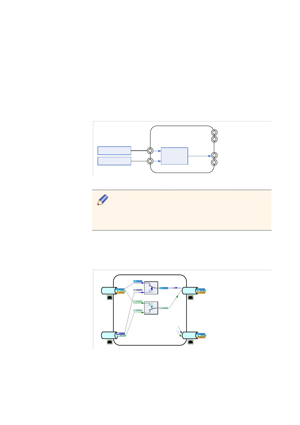
Figure 2-8. ASI wiring example
ASI In 2
ASI In 1
Switch
2 ASI Out for
monitoring
ASI Out 1
(smart-secured)
Equipment A
Equipment B
ASI Out 2
for stream duplication
Outputs can be smart-secured. Smart-secured outputs shall always
be connected (at least to the provided 75 Ohms stubs). Should they
not be connected, some input synchronization problems may
appear, resulting in invasive switching.
Refer to the
Section ’ASI Interfaces’
on page 196 for more
information.
To the
Ethx
connectors for Amethyst III with a Gigabit Ethernet
board.
Figure 2-9. Ethernet wiring example
Eth3
2 TS over IP
Eth1
2 TS over IP
Eth4
2 TS over IP
Eth2
2 TS over IP
Switch 1
Switch 2
output duplication (fully
configurable)
T
S
1
o
I
P
T
S
2
o
I
P
T
S1
'
o
I
P
T
S
2
'
o
I
P