343
OPUS Projektor Manual
CAN
The protocol consists of the following main elements:
·
unique identification of each participant on the bus
·
standardized message and number format for many automotive use cases
·
means to transfer data > 8 bytes (i.e. longer than one CAN message)
These main components are described in the following sections.
Based on these definitions there are more pages describing
·
basic settings to use J1939 ,
·
creation of J1939 ECUs and variables and
·
PGN mappings
in GUI tool to use J1939 on target display.
CAN Bus Configuration
J1939 is defined to run on a CAN 2.0B network at 250 kBit/s i.e. it uses long (29 bit) CAN
identifiers.
Message Format
J1939 describes each signal (i.e. each value to be transmitted) as an SPN (Suspect
Parameter Number).
Many SPNs are combined into a PGN (Parameter Group Number) which gets a unique
number and describes what is actually transmitted on CAN bus.
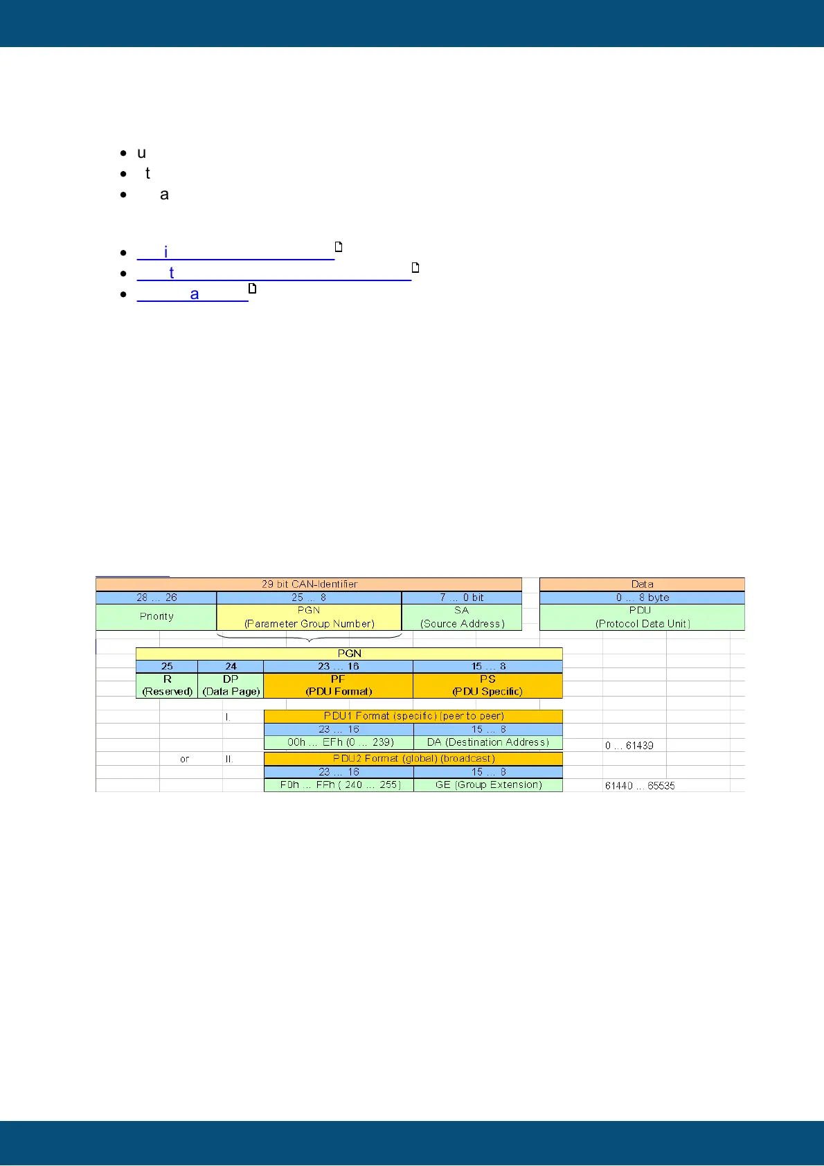
Each PGN can be identified by the CAN identifier which has the following format (source:
Wikipedia)
The last byte of this CAN ID always lists the source address of the message i.e. it identifies
the ECU which sent this message.
The first three bits are always considered priority based on CAN interpretation i.e. the
lower value indicates higher priority.
Located between these two is the 18 bit PGN value consisting of
1. Bit 25 was "reserved" in the past but is meanwhile considered "Extended Data
Page" (0 for most predefined PGNs)
2. Bit 24 defines the "data page"
SAE J1939 Page 0 Parameter Groups
SAE J1939 Page 1 Parameter Groups (NMEA2000 ®)*
*not supported by our devices
345
349
360