Installing
Grounding the device
Hans Turck GmbH & Co. KG | T +49 208 4952-0 | more@turck.com | www.turck.com
07.00 | 2022/09 | 21
5.5 Outdoor device installation
The device is UV resistant in accordance with DIN EN ISO 4892-2. Direct sunlight may cause ma-
terial wear and changes in color. The mechanical and electrical properties of the device are not
impaired.
To prevent material wear and color changes: Protect the device from direct sunlight with
protective panels.
5.6 Grounding the device
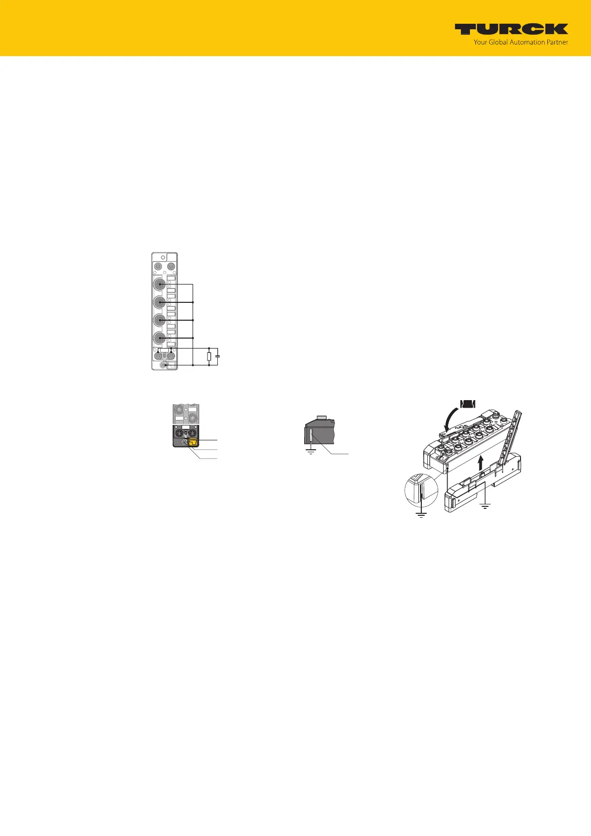
5.6.1 Grounding and shielding concept
The fieldbus and I/O area of the TBEN-S modules can be grounded separately.
Fig.8: Equivalent circuit, shielding concept
Fig.9: Grounding clip (1),
grounding ring (2) and metal
screw (3)
Fig.10: Grounding contact Fig.11: Grounding the TBNN-
S0-DRS… adapters
The grounding clip (1) on the M8 plug connectors for the fieldbus connection (P1, P2) connects
the shield of the fieldbus cables.
The grounding ring (2) provides the shield on the flange of the M8 plug connectors for the
fieldbus connection via an RC circuit.
When mounting the module on a mounting plate with TBNN-S0-STD connectors, the module is
connected to the reference potential of the installation via a metal screw (3) through the lower
mounting hole. The TBNN-S0-DRS adapters for mounting the TBEN-S modules on a DIN rail
(TS35) connect the grounding contact (4) of the modules with the DIN rail and thus FG.
 Loading...