Connection
Connecting digital sensors and actuators
Hans Turck GmbH & Co. KG | T +49 208 4952-0 | more@turck.com | www.turck.com
07.00 | 2022/09 | 30
6.5 Connecting digital sensors and actuators
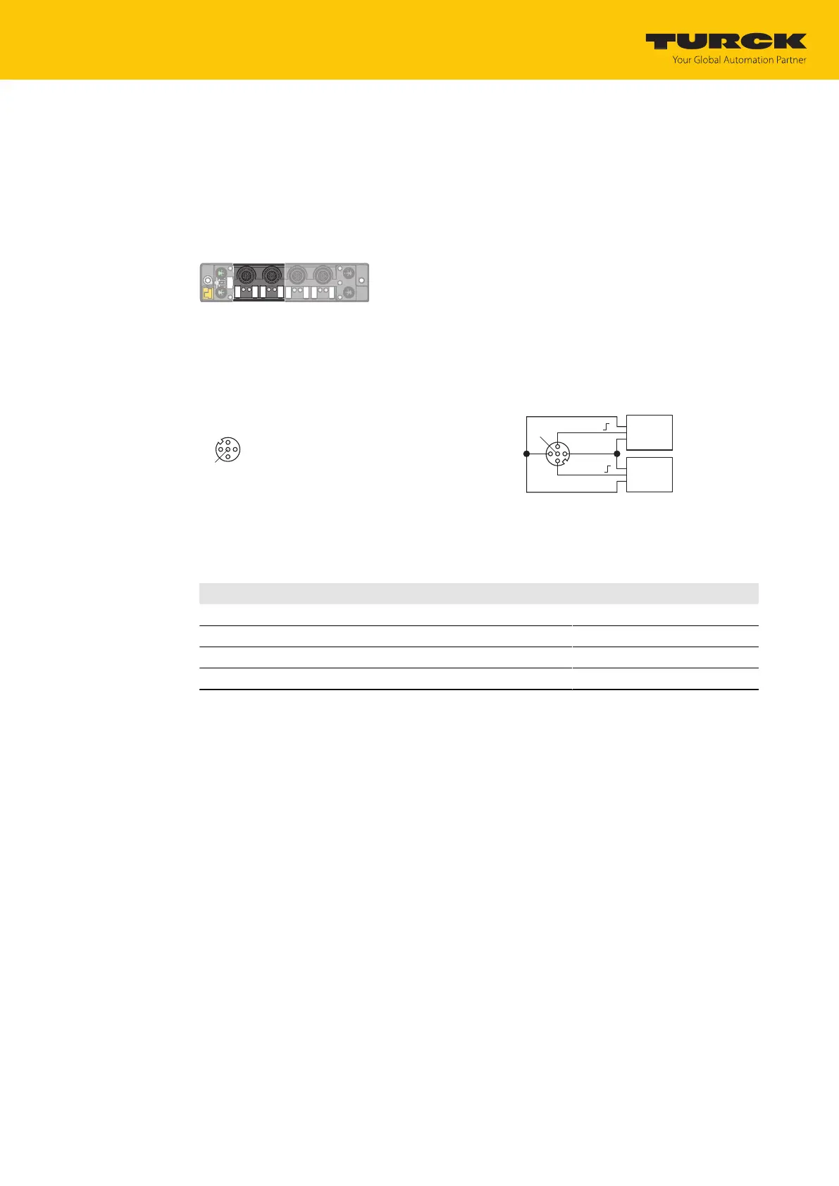
The device has two 5-pin M12 plug connectors for connecting digital sensors and actuators.
Sensors and actuators can be connected to the DXP terminals in the following combinations:
n 2 digital inputs
n 2 digital outputs
n 1 digital input and 1 digital output
Fig.25: M12 male connectors for connecting digital sensors and actuators
Connect the sensors and actuators to the device as per the pin assignment below.
Provide unused male connectors with suitable sealing or blanking caps. The tightening
torque for the M4 screws is 0.5 Nm.
4
1
3
2
5
v
1 = V
aux
2
2 = Signal In/Out
3 = GND V2
4 = Signal In/Out
5 = FE
C2...C3
5 FE
4 BK
1 BN +
3 BU –
3 BU –
2 WH
v
C2…C3
Sensor
or
Actuator
Sensor
or
Actuator
Fig.26: Connections for digital sensors and ac-
tuators — pin assignment
Fig.27: Connections for digital sensors and ac-
tuators — wiring diagram
The channels are assigned to the sockets as follows:
Channel Socket Pin
DXP (Ch4) C2 4
DXP (Ch5) C2 2
DXP (Ch6) C3 4
DXP (Ch7) C3 2
 Loading...