Connection
Connecting RFID read/write devices
Hans Turck GmbH & Co. KG | T +49 208 4952-0 | more@turck.com | www.turck.com
07.00 | 2022/09 | 27
6.4.1 Connecting read/write heads for the HF bus mode
In HF bus mode up to 32 bus-capable read/write heads per RFID channel can be connected to
the device. The user must determine by means of a power consumption analysis whether an
additional power supply is required for the connected read/write heads (see information in the
data sheet or tool at www.turck.com/hf-busmodus).
The maximum permissible length of the bus is 50m.
Connecting read/write heads for HF bus mode in non-Ex areas
The following devices are required for bus mode in non-hazardous areas:
n VT2-FKM5-FKM5-FSM5 junction box (ID 6930573) for connecting several read/write heads to
an RFID channel
n RSE57-TR2/RFID bus terminating resistor (ID 6934908)
n Optional: VB2-FKM5-FSM5.205-FSM5.305/S2550 junction box (ID 6936821) for feeding in an
additional power supply
n RFID extension cables (e.g. RK4.5T-0.3-RS4.5T/S2503)
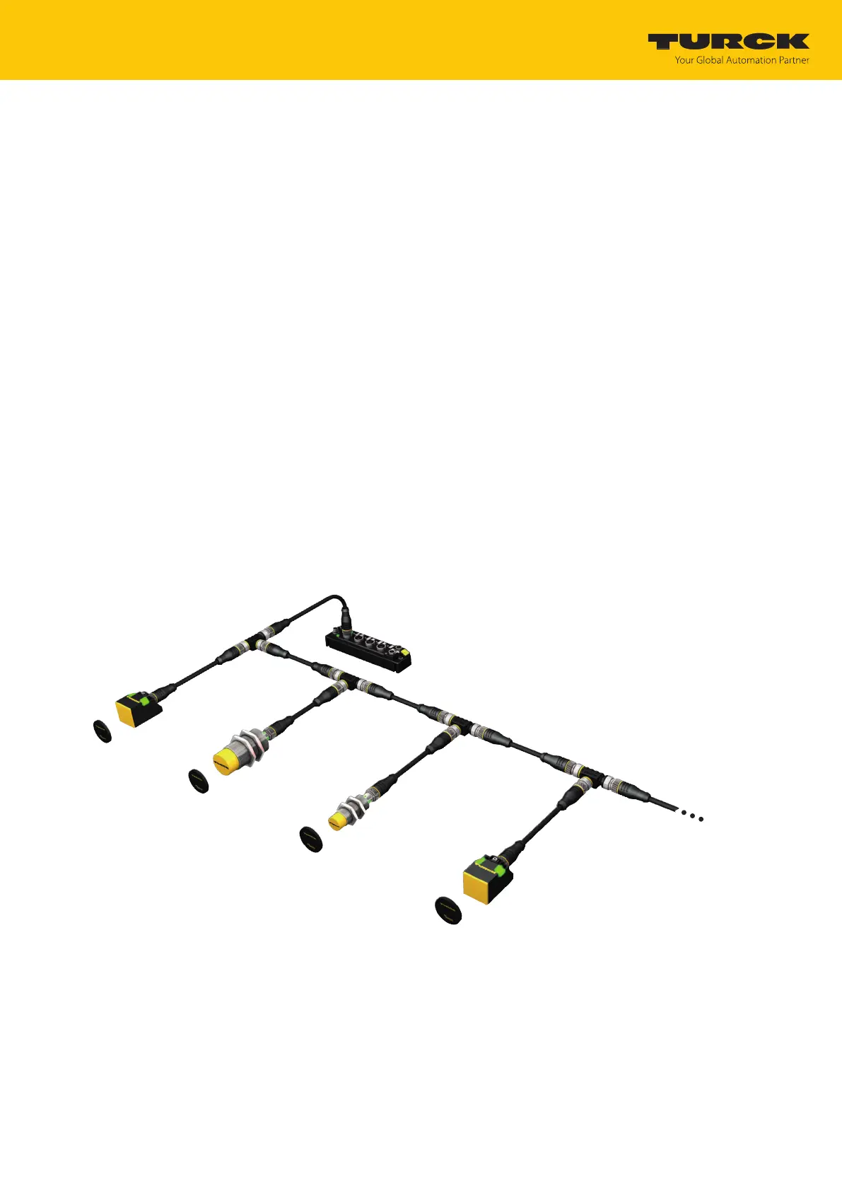
Connect the read/write head as per the figure below. The maximum length of the spur
line is 2m.
Make allowance for the power supply, particularly at switch-on (see data sheet), as well as
the maximum current carrying capacity of the lines (4A).
Make allowance for the voltage drop on the line. If necessary provide an additional
power supply between the read/write heads using junction box VB2-FKM5-FSM5.205-
FSM5.305/S2550.
Connect a terminating resistor (e.g. RSE57-TR2/RFID) after the last read/write head.
TBEN-S2-2RFID-4DXP
VT2-FKM5-FKM5-FSM5
RFID connection cable
(e.g. RK4.5T-0.3-RS4.5T/S2503)
TN-M18-H1147/C53
TN-CK40-H1147/C53
TN-M30-H1147/C53
up to 32 per port
Fig.23: HF bus mode setup
 Loading...