Setting
RFID channels — parameter data
Hans Turck GmbH & Co. KG | T +49 208 4952-0 | more@turck.com | www.turck.com
07.00 | 2022/09 | 90
8.1.3 HF applications — setting the bypass time
Due to the expansion of the HF transmission zone the tag may drop out momentarily during a
write or read operation and then later return again. The period between the drop out and the
return to the transmission zone must be bridged so that the write or read operation is com-
pleted. The bypass time is the time between the dropout and the return to the detection range.
The Bypass time parameter takes up oneword in the parameter data image and is stated in ms.
The bypass time can be set between 4…1020 ms. The bypass time parameter depends on the
components used, the write/read distances, the speed of the tag to the read/write head and
other external factors.
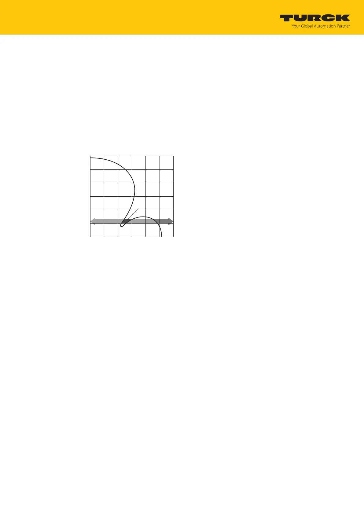
The following figure shows the typical characteristics of the sensing range and the path
covered by the read/write head. A shows the section to be bridged:
Fig.73: Detection range of a read/write head
Retaining the default setting
The default setting for the bypass time is 200ms. In HF bus mode the default value is 48 ms.
Retaining the default setting: If the commissioning is successful, the parameter does not
have to be adjusted to the application. If the commissioning is not successful, an error
message will appear.
If the error message appears, adjust the bypass time. If it is not possible to adjust the
bypass time, reduce the speed or data volume.
The information “Recommended distance” and “Maximum distance” is provided in the
product-specific data sheet.
Adapting the bypass time to the application
Measure the required bypass time directly on location. The LEDs of the read/write head
and the TP status bit indicate whether the read/write head is in the detection range or
not.
Enter the required bypass time.
 Loading...