Installing
Grounding the device
Hans Turck GmbH & Co. KG | T +49 208 4952-0 | more@turck.com | www.turck.com
07.00 | 2022/09 | 22
5.6.2 Grounding the device (FG)
Grounding clip and grounding ring are connected together.
If a common reference potential for I/O level and fieldbus level is not required: remove
the grounding clip to disconnect the fieldbus shield.
Grounding the device — mounting on DIN rail
When mounting on a DIN rail with the TBNN-S0-DRS adapters fasten the supplied metal
screw on the lower mounting hole of the TBEN-S module.
a The shield of the fieldbus connection and the M8 flange of the I/O level are connected via
the DIN rail with the reference potential of the installation.
Grounding the device — mounting on mounting plate
When mounting on a mounting plate, fasten with an M4 metal screw.
a The shield of the fieldbus connection and the M8 flange of the I/O level are connected via
the DIN rail with the reference potential of the installation.
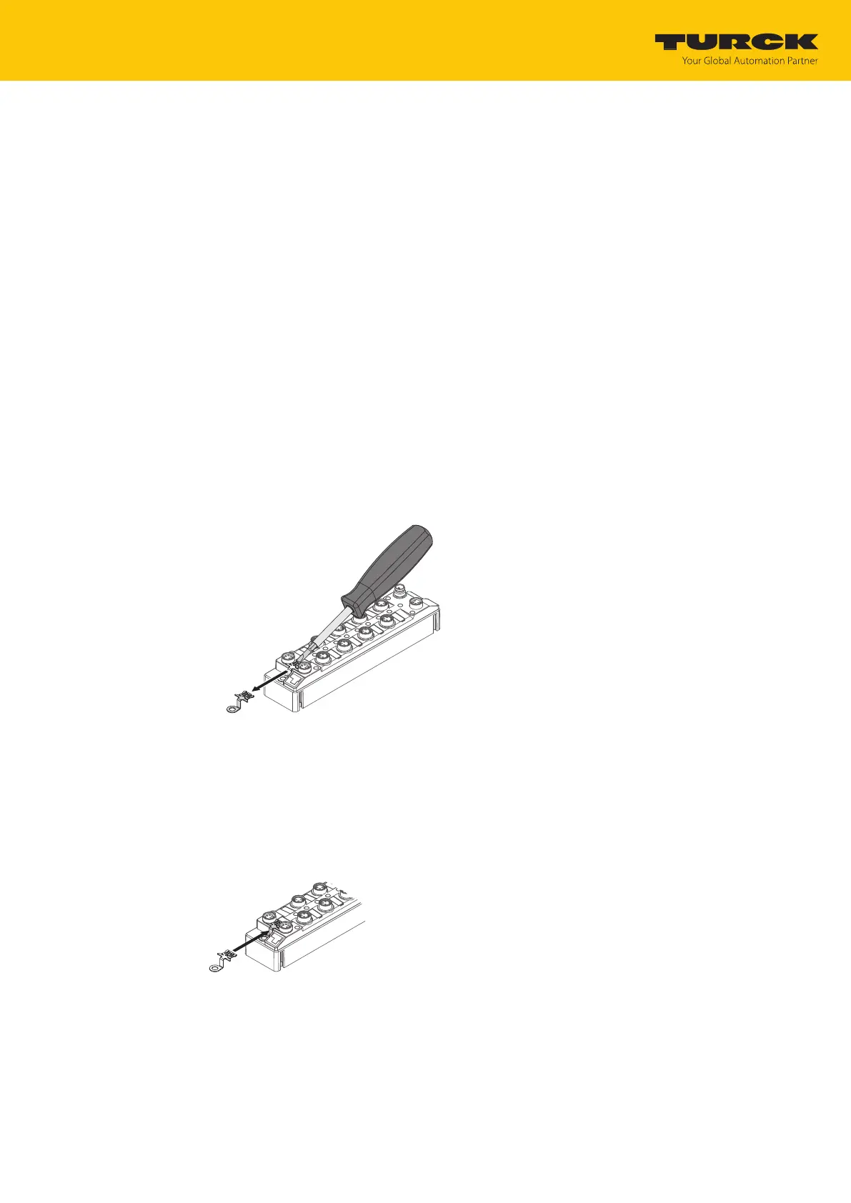
Removing the grounding clip
Push the grounding clip forward with a flat slot-head screwdriver and remove.
Fig.12: Removing the grounding clip
Mounting the grounding clip
Use a screwdriver to insert the grounding clip between the fieldbus connectors so that
contact is made with the metal housing of the plug connectors.
a The shield of the fieldbus cables is connected to the grounding clip.
Fig.13: Mounting the grounding clip
 Loading...