1225
Model Code Page
90. Hydraulic system
1. 8. 1998
6000--8750 910 15
8. 11. 1990
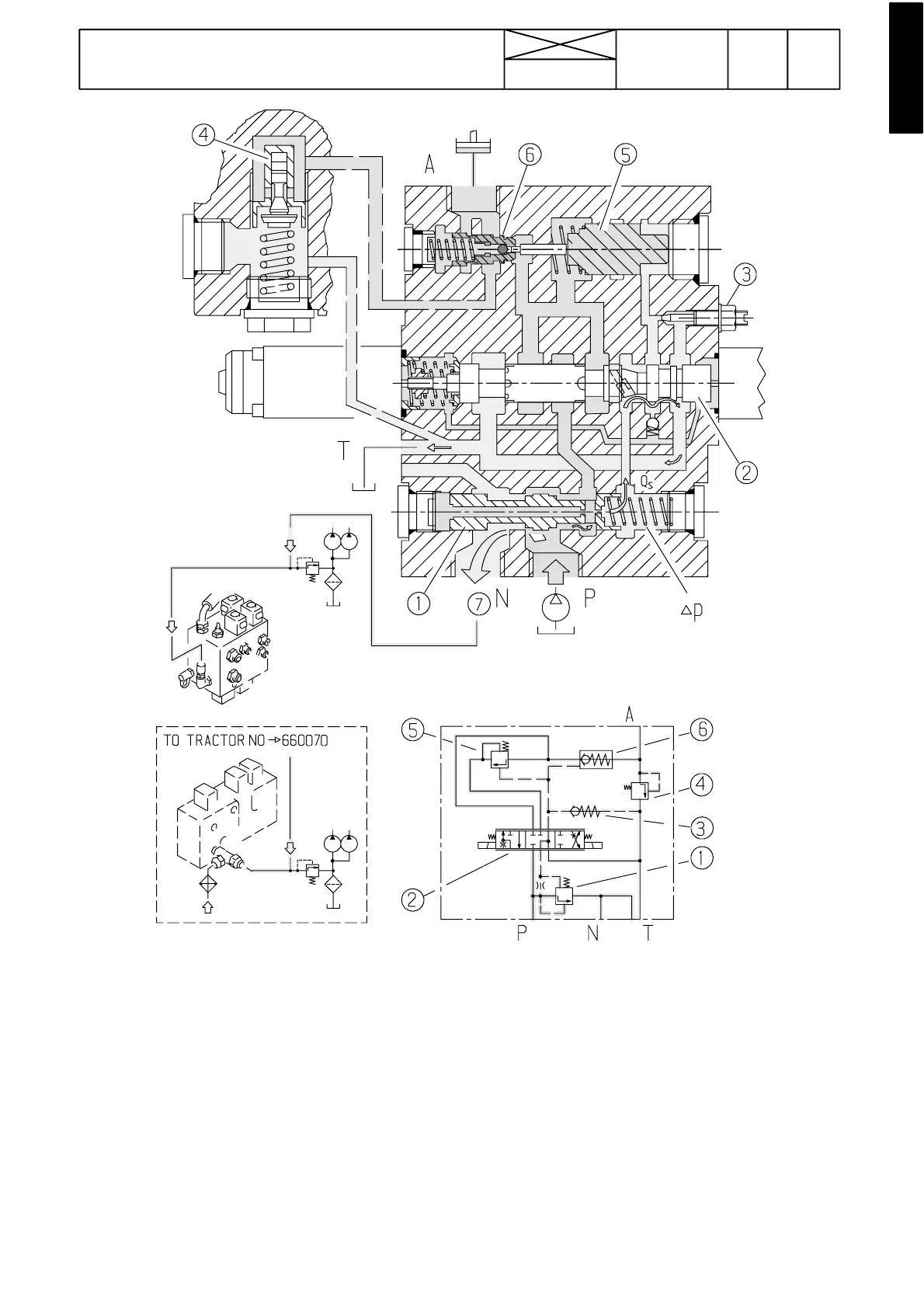
Figure 9. Control val ve in neutral position
Function (neutral position)
When the tractor is started oil flows from the pump (port ”P”)
to the left end of the spool (1) through a drilling in the middle.
The spool is then pushed to the right against a spring and
opens the unloading circuit between ports P and N ( pump---
tank)
Through the drilling in the spool (1) oil flows t hrough the dril-
ling at the right end of the slide. The constant o il (Qs) flows
via the main spool (2) to the tank (”port T”).
The main spool (2) is held in the middle position by the action
of the centring springs (left end of spool in fig 9) The pressure
(+spring) keeps the lowering valve ( 6) clo sed.
1) 3---way oil flow regulating slide
2) Main spool
3) Pilot pressure limiting valve for lowering valve
4) Shock valve
5) Lowering valve pilot piston.
6) Lowering valve
7) Free circulation oil to the transmission lubricating system