1226
Model Code Page
90. Hydraulic system
1. 8. 1998
6000--8750 910 15A
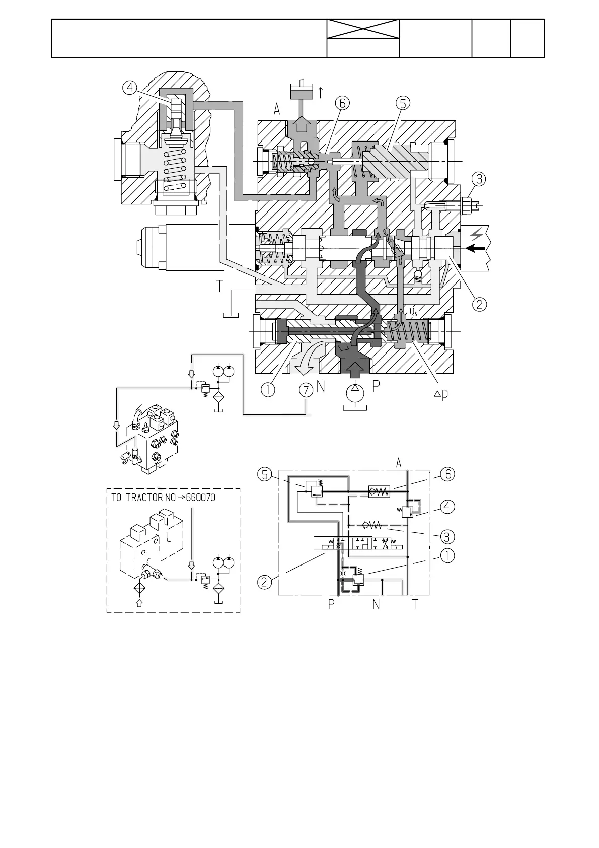
Figure 10. Control valve in the lifting position
Function (lifting position):
In the lifting position the RH solenoid is energized. The
magnet presses the main spool (2) to the left against the cen-
tring spring. Then it opens the passage from the spool (1) to
the lifting cylinders by an amount proportional to the strength
of the current supplied to the RH solenoid.
The right end of the slide (1) is under lifting cylinder pressure.
Pump pressure becomes equal in value to lifting cylinder
pressure + pilot pressure (=spring). The pressure difference
through the restriction of the main spool (2) is always equal to
pilot pressure so the oil flow depends only on the position of
the main spool (2) (and oil viscosity).
The lifting solenoid is controlled so that in the beginning and
in the end of the lifting movement, the solenoid current is cut
a period of some milliseconds, so that the movement be-
comessmooth. The actual lifting movement is carried outwith
full current (o therwise as in the lowering position).
1) 3---way oil flow regulating slide.
2) Main spool.
3) Pilot pressure limiting valve.
4) Shock valve.
5) Lowering valve pilot piston.
6) Lowering valve.
7) Free circulation oil to the transmission lubricating system.