1227
Model Code Page
90. Hydraulic system
1. 8. 1998
6000--8750 910 15B
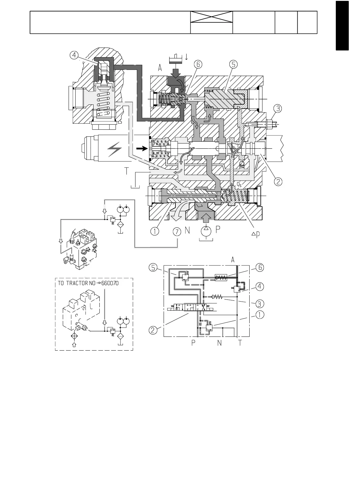
Figure 11. Control valve in the lowering position
Function (lowering position):
In the lowering position the LH side solenoid is energized.
The magnet presses the main spool (2) to the right against the
inner spring. The spool opens the passage between the
lowering valve (6) and tank (T).
At the same time the spool (2) also allows oil (Qs) to flow be-
hind the pilot piston (5). The piston moves to the left and
opens the lowering valve pilot ball. The pressure behind the
lowering valve decreases (compared with the pressure in the
working line) and the lowering valve opens and allows oil to
flow from the lifting cylinders to the tank.
The return oil flow pressure also acts on the front of the piston
(5). If this pressure reaches a sufficient level (greater than the
force of spring+pressure Qs), the holding valve stops the
flow.
Therefore the return flow does not depend on the pressure
causedby the load on the three point linkage. The rate (lower-
ing speed) of the return flow is proportional to the current
supplied to the solenoid for lowering. The pilot pressure limit-
ing valve (3) sets a pressure difference which acts over the
main spool (2) when the load is being lowered.
The free circulation circuit from the pump (P) to the tank (N)
functions as in the neutral position.
1) 3---way oil flow regulating slide
2) Main spool
3) Pilot pressure limiting valve
4) Shock valve
5) Lowering valve pilot piston
6) Lowering valve
7) Free circulation oil to the transmission lubricating system.