275
Model Code Page
31. Autocontrol 2.2 / 2.3
1. 8. 2000
314 36200--8150
1. 6. 1999
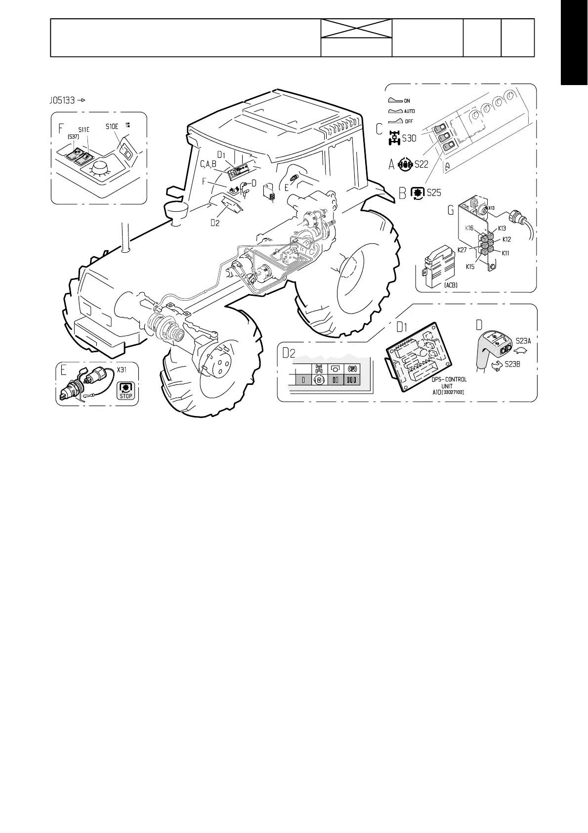
Picture 1. AC 2.2 / 2.3, components
A. Diff. lock rocker switch
B. PTO rocker switch
C. 4WD rocker switch
D. DPS push buttons in the speed gear lever knob
D1. DPS circuit card (A10, not HiTech) in connection with ACB
power lift switch panel. The circuit card is accessible after re -
moving the switch panel (see page 320/10).
D2. Combination instrument, in which there are DPS pilot
lights.
E. PTO emergency plug at the rear of the tractor
F. S10E: Lift/stop/lower ---switch (Autocontrol ---switch)
S11E: Forced lowering switch
G: Relay bracket in the lever console
Relays K 1 1 --- K 1 3 : Diff. lock control relays (relay K12 is not
fitted in AC 2.3).
Relay K15:4WDcontrolrelay
Relay K16:PTOcontrolrelay
There is a relay K7 in the fuse box for the four wheel brak-
ing.
Relay K27:4WDcontrolrelay
Note! In the relay bracket there can also be other relays
depending on the tractor equipment (e.g. HiShift---relay
K24, Control stop relay K18 and/or SigmaPower relay K19).
Note! The wire looms of the AC 2.2/2.3 tractors have been
standardized with the wire looms of HiTech ---models. Thus
there is a connector bracket in the lever console. E.g. sole-
noid valve connector X13 is no more placed under the par-
king brake console, but X13 is a 37---pole connector in the
lever console (as in HiTech---tractors).