min
max
max
extra
Oil level
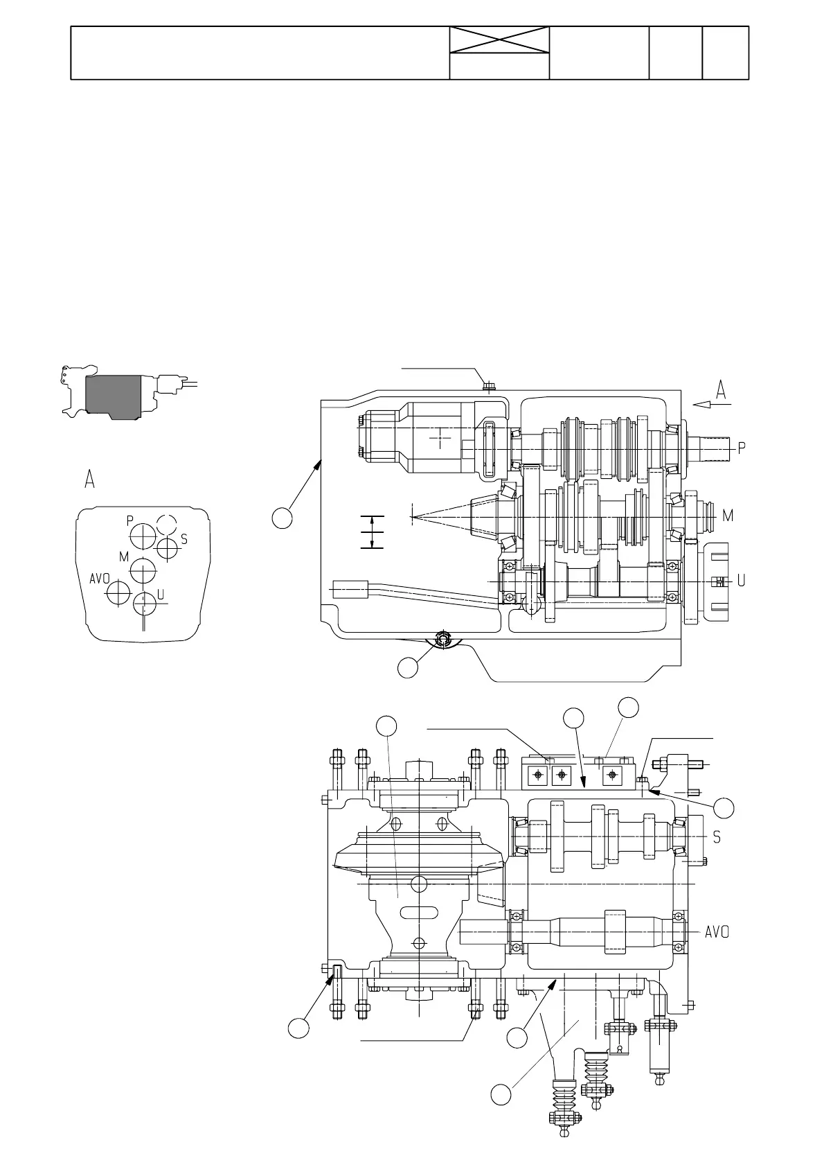
Gearbox front side
Figure 2. Gea rbox
P=input shaft
S=layshaft
M=bevel pinion shaft
U=transmission shaft
AVO=ground speed PTO shaft (optional)
1. Sealing Hylosil RTV Grade 102 Black
2. Gasket
3. Locking fluid Loctite270
4. Draining plug (oil change and suction strainer
cleaning at intervals of 1000 running hours).
5..Differential
6. Selector cover
7.Servovalveblock
672
Model Code Page
42 Gearbox
1. 1. 1995
6420
6000--8750
8. 11. 1990
Gearbox has four shafts (or five if ground speed PTO)
--- i np u t sh a f t ( P)
--- l a y sh af t (S)
--- bevel pinion s haft (M)
--- transmission shaft (U)
--- ground speed PTO shaft (AVO), optio nal
In the lower part of the gearbox there is fitted a transmission
shaft (U), which transmits LL---range to the pinion shaft and
power to the ground speed PTO shaft (optional). There is a
4WD gear and 4WD clutch drum fitted in the front end of the
transmission shaft. Po wer to the 4WD clutch drum is trans-
mitted from the gear at the front end o f the pinion shaft.
Selector fork for the ground speed P TO is fitted on the pinion
shaft (M). The ground speed PTO fork is operated with the
PTO control lever.
Input shaft (P), layshaft (S) and pinion shaft (M) are supported
in taper roller bearings, ground s peed PTO shaft (AVO) and
transmission shaft (U) in ball bearings.
Input shaft and pinion shaft have pressure lubrication. Other
shafts are lubricated through splash lubrication.
In the rear end of the input shaft thereis a pump driving mech-
anism which is powered by a long drive shaft from the fly-
wheel. Input shaft front end splines engage to the reverse
shuttle gear splines.
End float for the input shaft and layshaft is adjusted with
shims in the front end of the shafts. Pinio n shaft bearing pre-
load is adjusted with spacer rings (2 pcs) at the front end of
the shaft. Position of the pinion shaft is adjusted with shims
under the shaft rear bearing outer race.
40---50 Nm
40---50 Nm
270---330 Nm
90---110 Nm
3
1
1
2
1
4
5
6
7