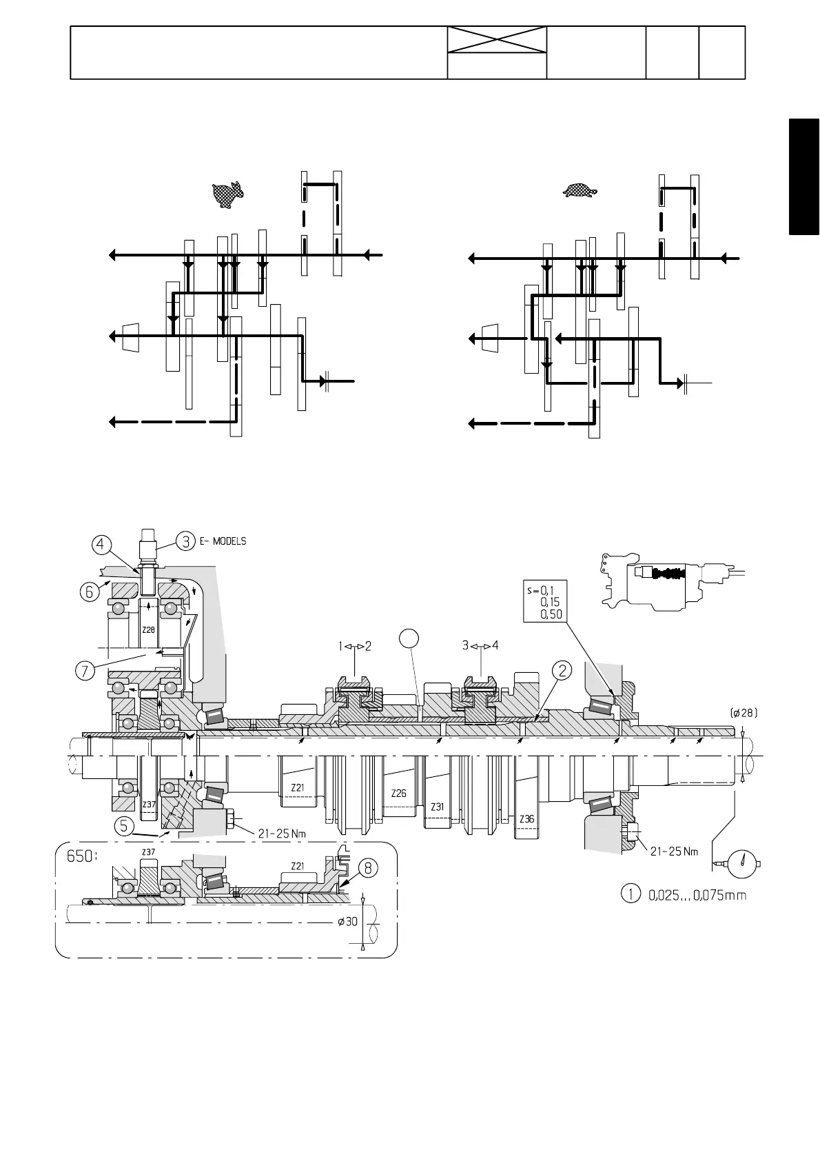
Figure 3. Power route in ranges H and M
Figure 4. Power route in range LL
Figure 5. Input shaft (P)
1. Bearing end float is adjusted with shims
2. Bushing is locked with Loctite 601
3. Engine speed sensor (only 6600E and 8100E)
4. Sensor threads are locked with Loctite 542 (only 6600E and 8100E)
5. Lubricating oil to the input shaft
6. Splash oiling from crown wheel
7.Lubricating oil to pump drive shaft splines
Note! In the 650 transmission the input shaft rearmost bearing is larger. Also the input shaft is different in the transmissions
300 and 460 due to the thicker pump drive shaft of the 650. In addition, gearwheel Z21 has been made broader. Spacer
ring A has been added between gears Z26 ---Z31. Adjust the clearance beween circlip (8) and synchro hub to zero or as
small as possible.
A (transmission 650). Thickness of
spacer:
3,50 mm (without dot)
3,65 mm (1 dot)
3,80 mm (2 dots)
3,95 mm (3 dots)
4,10 mm (4 dots)
673
Model Code Page
42 Gearbox
1. 8. 1998
7420
6000--8750
15. 5. 1996
P ower routes in gearbox
4321PTO
M
4WD
AVO
R
4321PTO
R
4WD
AVO
H
P
S
M
U
AVO
LL
Gearbox shafts
B4C
A