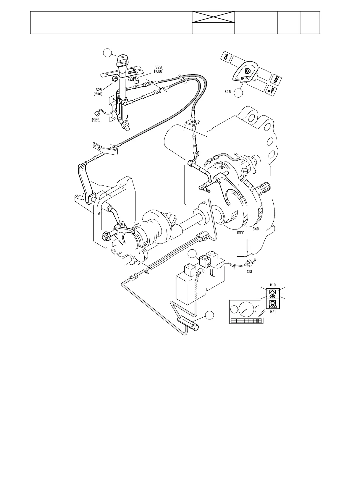
Figure 7. Engagement of PTO up to ser. no. 660070
1. Control lever
2. Switch
3. Solenoid valve
4 . Cushioning valve
824
Model Code Page
46. Power take ---off
15. 5. 1993
6000--8750 460 10
8. 11. 1990
1
3
4
2
Lever (1) movement is transmitted via a cable to the selector
fork on the PTO unit slidingcouplerand alsovia another cable
to the selector fork on the sliding coupler (in gearbox) for
ground speed PTO (optional).
When the control lever is in the middle position, the PTO unit
sliding coupler is in the middle position, PTO clutch is unpres-
surised and the PTO brake is engaged.
When the lever (1) is moved to the front position (engine PTO
540 r/min), the sliding coupler in the PTO unit is moved to the
rear position and when the lever is released, the lever presses
the microswitch, which in turn connects current tothe PTO so-
lenoidvalve and the PTO clutch is engaged and the PTO shaft
starts to rotate (indicator light comes on).
When the engine speed PTO is disengaged, first the micro-
switch disconnects the solenoid valve and the PTO clutchdis-
engages (and t he brake engages). When the lever is moved
to the middle position, the sliding coupler is moved to the
middle position. (indicator light goes out)
In the same way is engaged engine PTO 1000 r/min. Now the
lever is moved to the rear position. Indicator light in the instru-
ment panel is lit.
Ground speed PTO is engaged by moving first thelever tothe
left from the middle position and then backwards. Now the
sliding coupler in the gearbox engages the ground speed
PTO mechanically. Now the PTO clutch is in the disengaged
position (unpressurised).
There is a switch on the PTO control lever knob. With this
switch the PTO clutch can be disengaged temporarily. The
sliding coupler, however, does not move to the middle posi-
tion. Long---periods of disengagement should always be
done with the control lever