239
Model Code Page
51. Brake system
1. 9. 2002
6000--8950 511 1
8. 11. 1990
Reconditioning brakes (Op. no. 511)
1. Service brakes
A. Changing brake discs
Note! There are oil grooves on the friction surface of the
brake discs. On new discs the grooves are 0,3 mm deep. If
thegroovesarewornaway,thebrakingefficiencywillbe
impaired and the discs should be replaced.
1. Remove the final drives (see Op. 451 1A).
2. Pull out the inner drive shaft. Remove the o uter support
plateinfrontofthediscs.
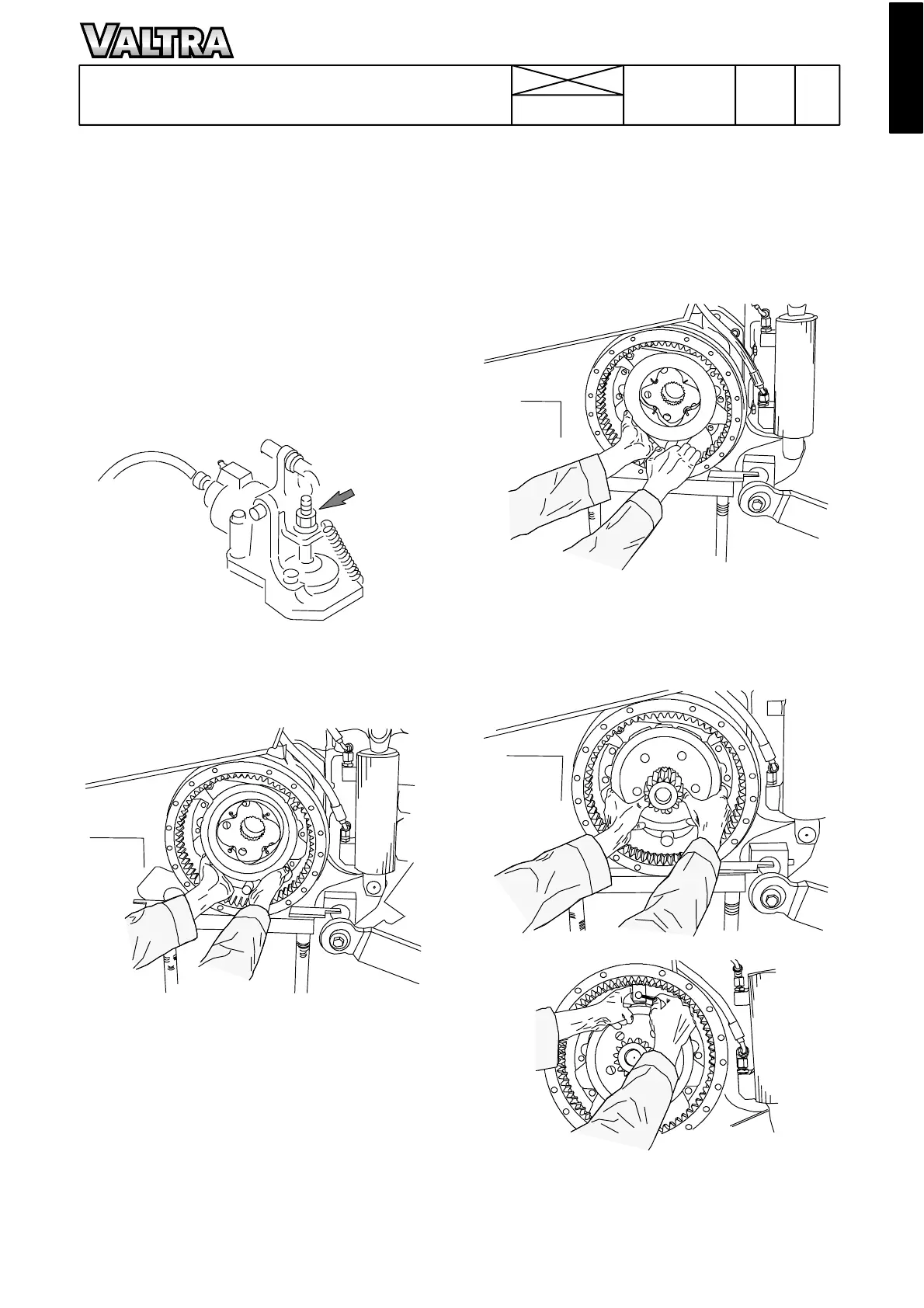
3.Removetheouterbrakediscs.
4. Slacken the adjusting nut (see arrow) until the brake
mechanism is loose.
5. Take out the cotter pin and the link pin at the lower end o f
the stay. Pull the stay up until it is free from the application
plate.
5a. Final drives 300, 450, 650: Remove the application
plates by simultaneously pulling out the anchor bolt, fitted
under the plate, and loosening the lower end of the plate
from its position.
Note! The removal of the applic ation plates is easier if the
outermost circl ip is removed from the anchor bolt.
5b. 8350---8950Hi with final drives 700 has not an anchor
bolt . Pull the application rings out of the housing.
6. Remove the inner brake discs.
7. Chec k the friction surfaces in t he brake housing and pol-
ishwithanemerycloth.
8a. Final drives 300, 450, 650: Push the anchor bolt in
through the hole in the brake housing, but do not press it
right home. Fit the inner brake discs on the anchor bolt.
Check t hat the discs remain located in front of the inner
circlip.
8b. In connection with final drives 700 there is not the an-
chor bolt. Place the inner brake discs and the intermediate
discs in position so that the lugs engage into the grooves
on the brake housing.
9. Final drives 300, 450, 650: Insert the application plate
into the housing with the upper edge first locating the lower
edge of the plate on the pulled ---out anchor bolt. Press the
bolt and the application plate into position. Fit the outer
circlipontheanchorbolt. Inconnectionwithfinaldrives
700, pass the application plate into place so that lugs on it
engage into the grooves in the housing.
11. Us ing the link pin connect the brake stay to the link
arms of the application plate and secure with the cotter pin.
Tighten the adjusting nut at the upper end of the stay.