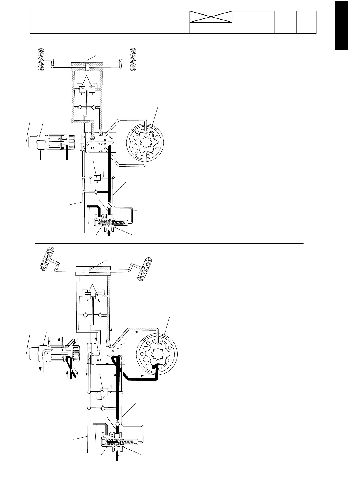
Figure 2. Steering wheel is not turned
1. Steering wheel
2. Spool valve
3. Rotor
4. Steering cylinder
5. Pressure---limiting valve (14 MPa)
6. Shock valves (19,5 MPa)
7. Priority valve
8. Priority valve slide
P=From pump
T=To tank
CF=Pressure oil to steering valve
EF=Pressure oil to working hydraulics
HP=Low ---pressure oil from servo valve block, ---660070
LS=Load sensing line
In this figure the steering wheel is not turned. LS line is
unpressurized and the slide (8) in the priority valve directs
oil pressure to th e line EF (to the working hydraul i c s)
Figure 3. Steering wheel is turned to the right
1. Steering wheel
2. Spool valve
3. Rotor
4. Steering cylinder
5. Pressure---limiting valve (14 MPa)
6. Shock valves (19,5 MPa)
7. Priority valve
8. Priority valve slide
P=From pump
T=To tank
CF=Pressure oil to steering valve
EF=Pressure oil to working hydraulics
HP=Low ---pressure oi l from servo valve block, ---660070
LS=Load sensing line
In this figure the steering wheel is turned and the pipe LS
is pressurized and pushes the slide (8) so that pressure
from pump P is directed to the steering valve (pipe CF)
and further to the steering cylinder. The pressure limiting
valve (5) regulates the steering system pressure at 14 MPa.
933
Model Code Page
61. Steering system
15. 5. 1993
6000--8750 610 5
8. 11. 1990
4
6
1
2
3
5
LS
T
CF
EF
P
HP
8
7
4
3
LS
5
2
1
T
HP
P
7
8
CF
EF
6