TITANUS MICRO·SENS
®
Installation
MS_A_05-en-e Data: 01/09 5 – 27
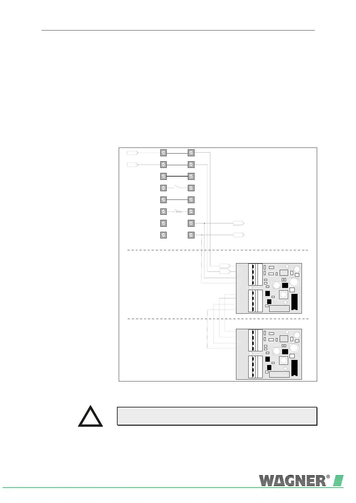
5.10.3 Electrical connection
Connect the parallel displays via the terminal block 7b and 8b indicator
bus on the device base unit of the TITANUS MICRO·SENS
®
. The power
is supplied via TITANUS MICRO·SENS
®
or for greater distances, exter-
nally. Calculate the lines as for TITANUS MICRO·SENS
®
, in accordance
with Chapter 4.8 "Power Supply".
You must comply with the permitted cable cross-sections for the particu-
lar cable throughputs and the permitted wire cross-sections for the termi-
nals (see Chapter 3 "Technical Data ").
Parallel display Connect the parallel display to the TITANUS MICRO·SENS
®
with the
power off as follows:
X1
X2
X3
1
2
3
4
1
2
3
4
+24V
0V
A
B
Data
+24V
0V
A
B
Data
1a
2a
3a
4a
5a
6a
7a
8a
1b
2b
3b
4b
5b
6b
7b
8b
Indicator bus
0V
+ 24V
0V
+ 24V
X1
X2
X3
1
2
3
4
1
2
3
4
+24V
0V
A
B
Data
+24V
0V
A
B
Data
Parallel display housing
Device Base detection unit
next Parallel display housing
Fig. 5.25: Connecting the parallel display to TITANUS MICRO·SENS
®
Maximal 2 relay boards or remote display units can be connected to the
device.
INSTRUCTION