TITANUS MICRO·SENS
®
Installation
MS_A_05-en-e Data: 01/09 5 – 23
5.9 TITANUS MICRO·SENS
®
in a network
Several TITANUS MICRO·SENS
®
can be connected optionally into a net-
work. This network system allows the user to monitor the status of all
connected TITANUS MICRO·SENS
®
. For this, for example, the pattern of
smoke levels, air flow values and the alarm and fault status are
transmitted via the bus system.
To operate the TITANUS MICRO·SENS
®
in a network, special PC soft-
ware and a network module for additional housing are required which are
not supplied with the TITANUS MICRO·SENS
®
.
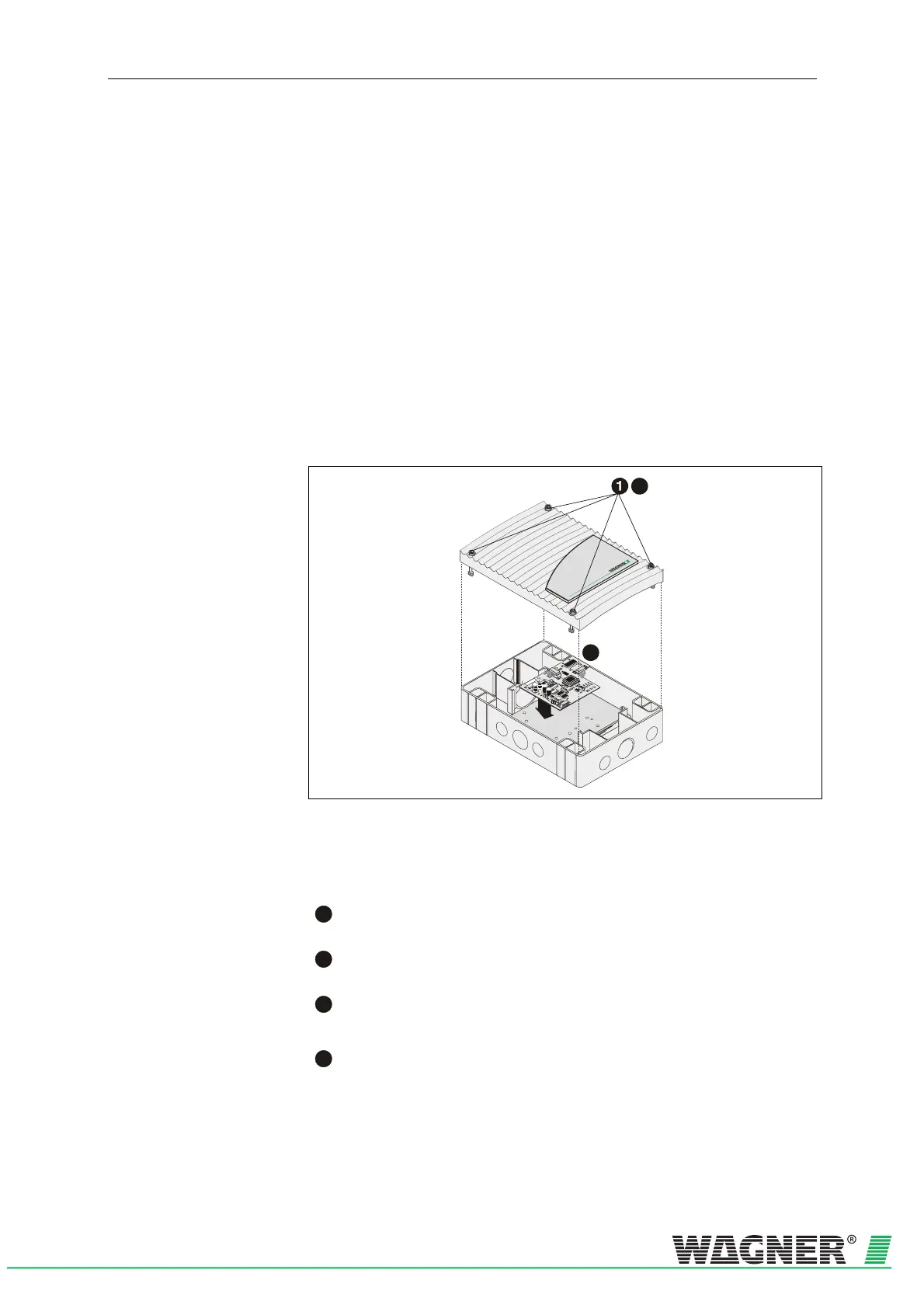
5.9.1 Fitting the network module into the
TITANUS MICRO·SENS
®
additional housing
4
3
Fig. 5.21: Fitting the network module into the additional housing
To fit the network module, first open the additional housing. The following
steps are to be taken:
1
With the aid of a screwdriver, loosen the four screws on the
additional housing cover.
2
Fit the network module into the TITANUS MICRO·SENS
®
addi-
tional housing
(for fixing points see Fig. 5.8).
3
The network module is connected as per Fig. 5.22.
Push the network cable into the RJ45 socket.
4
Refit the cover using a screwdriver to screw the four screws on the
device cover firmly
.

 Loading...

