Installation TITANUS MICRO·SENS
®
5 – 28 Data: 01/09 MS_A_05-en-e
5.11 Reaction indicator
5.11.1 Addressing the reaction indicators
ON
1
TEST
X3
12
+- A B
12
S1
ON
1
S1
2
3
4
5
6
Reaction indicator A
Reaction indicator B
Reaction indicator C
Reaction indicator D
Reaction indicator E
Permanent or flashing light
Te s t
Perma n ent or f l a s hi ng l i ght
A
B
C
D
E
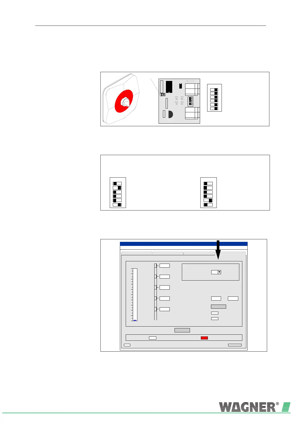
Fig. 5.26: Reaction indicator board with fire location
Addressing the up to 5 reaction indicators happens by setting up switch
S1 on the board.
ON
1
S1
2
3
4
5
6
A
B
C
D
E
Example :
Reaction Indicator B
Flashing light
ON
1
S1
2
3
4
5
6
A
B
C
D
E
Example :
Reaction Indicator E
Permanent light
Reaction indicator A
Reaction indicator B
Reaction indicator C
Reaction indicator D
Reaction indicator E
Permanent or flashing light
Reaction indicator A
Reaction indicator B
Reaction indicator C
Reaction indicator D
Reaction indicator E
Permanent or flashing light
Fig. 5.27: Example of addressing the reaction indicators
The reaction indicators are tested using the diagnostic tool (see Chapter
7 Commissioning).
File Record Settings ?
TITANUS
MICRO · SENS
®
Recep tion Serial No.
Device-S election
Cancel
Smoke level
10
9
8
7
6
5
4
3
2
1
0
min s
10
Te s t m o d e a c t i v e
Seat o f fire not estab lished
Start
(Date Time)
00000
s
s
s
s
s
E
D
C
B
A
Fault messages
Status Settings ROOM-IDENT
Seat of fire established
Establish seat of fire
Pre selection time
Measuring active
Test external indicators
Off
Indicator selection
Off
Current setting
Fig. 5.28: Testing the reaction indicators by menus of the diagnostic tool

 Loading...

