TITANUS MICRO·SENS
®
Installation Pipe System
MS_A_06-en-e Data: 01/09 6 – 9
6.4 Monitoring in forced air flow systems
(ventilation or climatic applications)
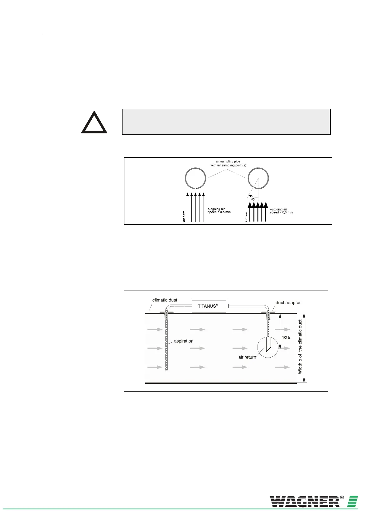
6.4.1 Detection at air inlets/outlets
If aspiration takes place in a forced air flow system (ventilator, climatic
systems), the air sampling points must be positioned in the air flow. Pla-
ce the air sampling points as shown in fig. 6.5.
Fig. 6.5: Positioning of air sampling point, depending on air speed
6.4.2 Detection in bypass systems
For connection of air return refer to chapter 6.6 "Air Return".
Fig. 6.6: Positioning of air return, example of a climatic duct (bypass)
For the pipe design of TITANUS MICRO·SENS
®
in these areas see chap-
ter 4.3.4 “Pipe Design for Forced Air Flow“.
INSTRUCTION

 Loading...

