TITANUS MICRO·SENS
®
Installation
MS_A_05-en-e Data: 01/09 5 – 31
5.13 Settings
5.13.1 Detection Unit
All settings are undertaken using the diagnostic tool. Installation of the
diagnostic tool for TITANUS MICRO·SENS
®
and its application are de-
scribed in Chapter 7.
?
TITANUS
MICRO · SENS
®
LOGIC·SENS
%/m
s
%
min
s
m
hPa
V
Cancel
Set
Active Initialisatio n
StandardAssume
+
-
+
-
+
-
+
-
+
-
0,500
10
50
140
0
1013
9,0
00000
File Record S ettings Device-Selection
(Date Time)
Fault messagesStatus Settings ROOM-IDENT
Recep tion
Serial No.
Fault lat ched
ROOM-IDENT
Dynamic air flow
Sensitivity (fire alarm)
Alarm delay
Air flow range
Fault delay
Height above sea level
Air pressure
Fan v olt age
%
+
-
60
Action alarm threshold
Fire alarm after
ROOM·IDENT
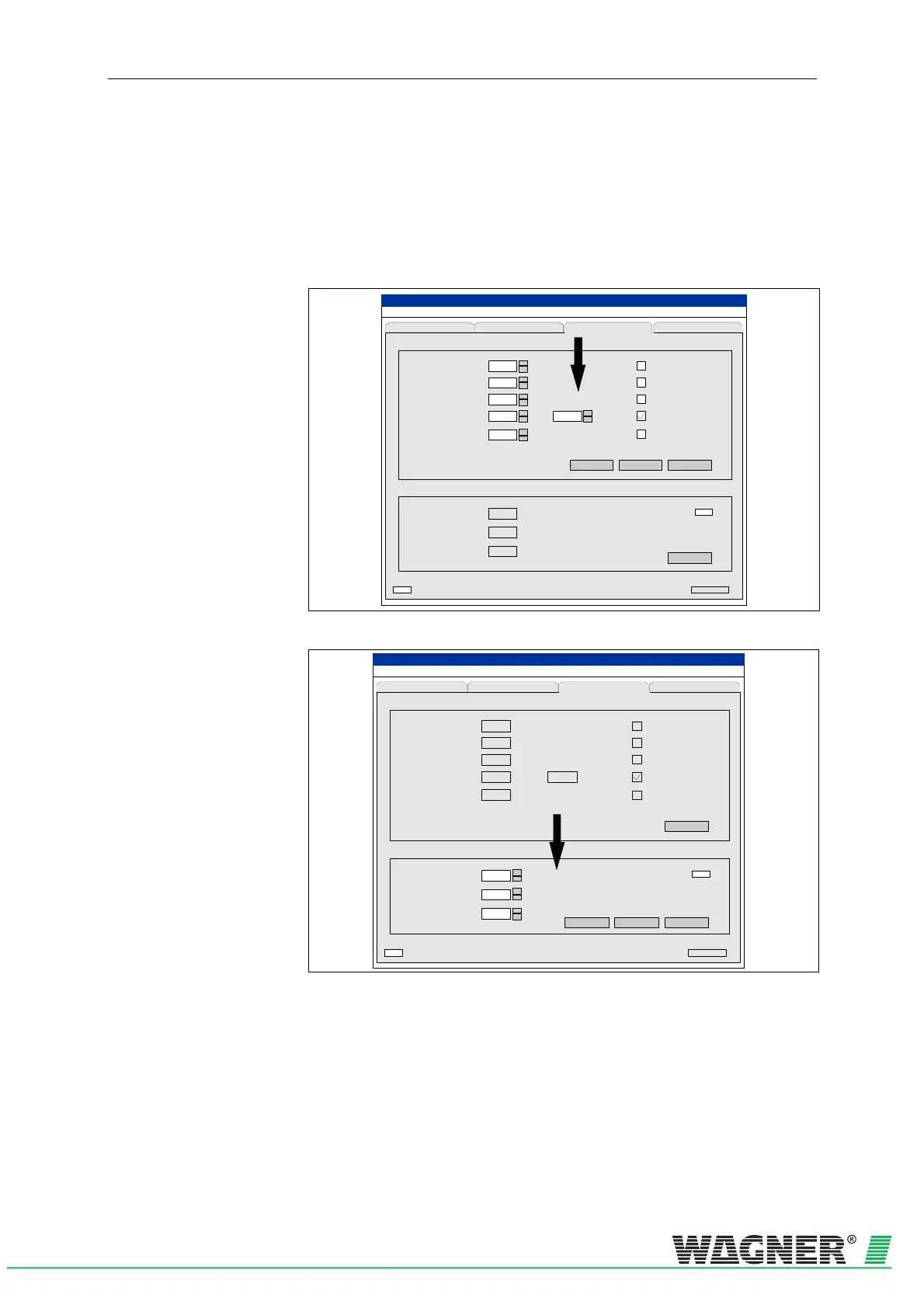
Fig. 5.31: Sensitivity, Alarm Delay, Air Flow Area and Fault Delay settings
?
TITANUS
MICRO · SENS
®
m
hPa
V
+
-
CancelStandard
Initialising
LOGIC SENS
%/m
s
%
min s
+
-
+
-
0,500
10
50
140
0
1013
9,0
00000
File Record Settings Device-Selection
(Date Time)
Fault messagesStatus Settings ROOM-IDENT
Receptio n
Sensitiv ity (fire alarm)
Alarm delay
Air flow range
Fault d elay
Height above sea level
Air pressure
Fan v o ltag e
LOGIC SENS
Set
Active Initialisation
Serial No.
Fault latched
ROOM-IDENT
Dynamic air flow
%
60
Action alarm threshold
Fire alarm after
ROOM·IDENT
Fig. 5.32: Height, Air Pressure and Fan Voltage settings
In the diagnostic software, the current TITANUS MICRO·SENS
®
figures
are displayed on the Settings screen.
The figures can be changed by pressing the Settings button.

 Loading...

