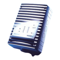
TITANUS MICRO·SENS
®
Installation
MS_A_05-en-e Data: 01/09 5 – 29
5.11.2 Connecting the reaction indicator to the
TITANUS MICRO·SENS
®
Connect the reaction indicators via terminal block 7b and 8b indicator bus
on the TITANUS MICRO·SENS
®
device base unit. The power is supplied
by the TITANUS MICRO·SENS
®
.
1a
2a
3a
4a
5a
6a
7a
8a
1b
2b
3b
4b
5b
6b
7b
8b
Indicator bus
Reaction indicator housing
0V
+24V
0V
+24V
ON1
TEST
X3
1
2
+-
A
B
1
2
S1
ON
1
TEST
X3
1
2
+-
A
B
1
2
S1
ON
1
S1
2
3
4
5
6
A
B
C
D
E
ON
1
S1
2
3
4
5
6
A
B
C
D
E
Device Base detection unit
Reaction indicator housing
Example :
Reaction Indicator B
Flashing light
Example :
Reaction Indicator E
Permanent light
Reaction indicator A
Reaction indicator B
Reaction indicator C
Reaction indicator D
Reaction indicator E
Permanent or flashing light
Reaction indicator A
Reaction indicator B
Reaction indicator C
Reaction indicator D
Reaction indicator E
Permanent or flashing light
Fig. 5.29: Connecting the reaction indicators to TITANUS MICRO·SENS
®

 Loading...