Installation TITANUS MICRO·SENS
®
5 – 12 Data: 01/09 MS_A_05-en-e
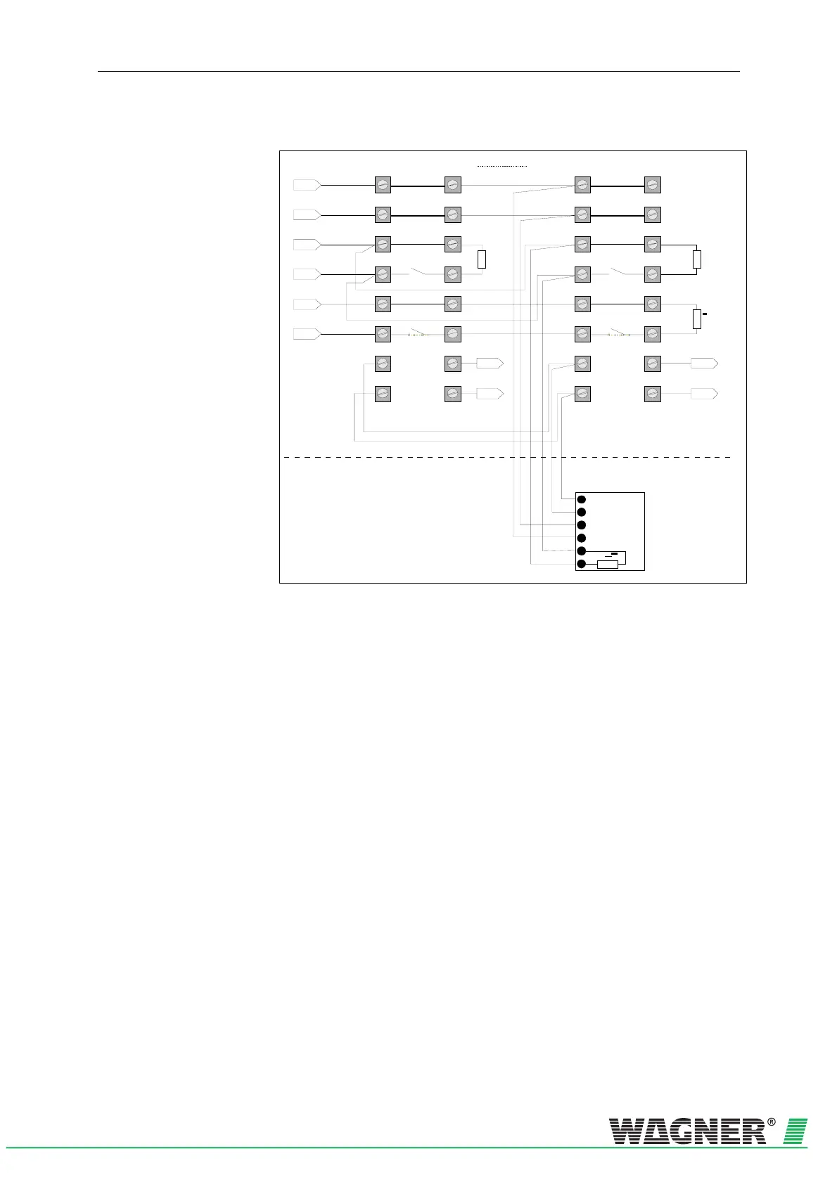
5.5.1 Connection to a CFDU, with reset board
Faul t+
Faul t-
L1-
L1+
0V
1a
2a
3a
4a
5a
6a
7a
8a
1b
2b
3b
4b
5b
6b
7b
8b
+ 24V
R
A
1a
2a
3a
4a
5a
6a
7a
8a
1b
2b
3b
4b
5b
6b
7b
8b
R
A
R
E
1
2
3
4
5
6
R
- Ub
+ Ub
+ Reset
- Reset
Reset plate I
Resistance R is to be calculated.
For formula see Chapter 5.7.
ER
1)
The reset plate must always
be mounted in the last device on the line
Additional housing
Device Base detection unit
1
bl
ge
gn
vi
R
sw
Device 1 Device n
Indicator bus
Indicator bus
Resistances depend
on the FAS connected
Fig. 5.11: Example of connecting a TITANUS MICRO · SENS
®
to a CFDU and reset board