TITANUS MICRO·SENS
®
Pipe Design
MS_A_04-en-e Data: 01/09 4 – 31
4.3.3 Design for Forced Air Flow
Monitoring air
conditioning ducts Air conditioning plants are divided into low-speed and high-speed plants
(see table below). The information given in this chapter applies only to
low-speed plants. There is insufficient information from experience with
high-speed plants. Where air conditioning ducts have flow speeds of
more than 10 m/s, therefore, smoke testing must be carried out for the
best reaction behaviour to be determined.
Low speed plants High speed plants
Flow speed maximum 6 to 10 m/s > 10 m/s
Duct cross-section large small
Differential pressures
along the flow direction
small large
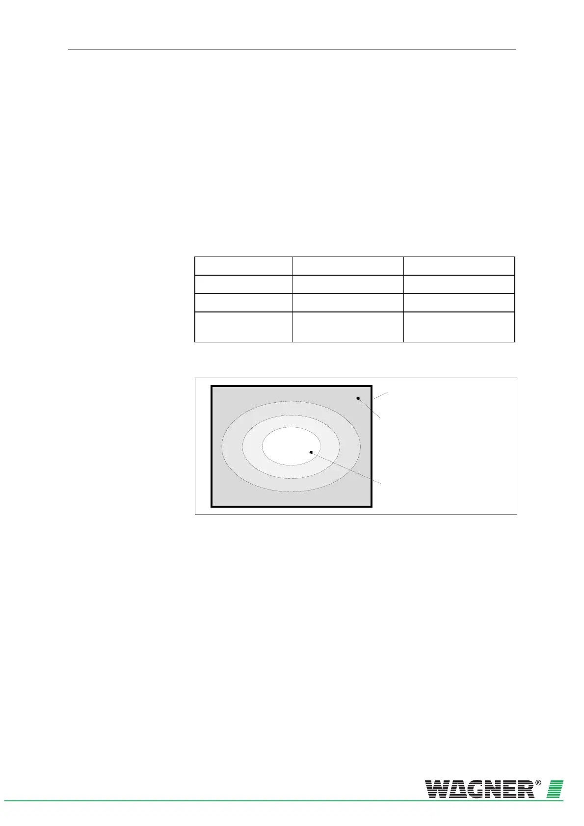
The speed distribution in an air conditioning duct looks as follows:
The largest air flow is t in the centre
of the cross section
Air conditioning duct
In the outer areas of the cross-section
surface area the air flow is lowest
v
1
v
2
v
3
v
4
Fig. 4.14: Speed distribution in an air conditioning duct with v
1
> v
2
> v
3
> v
4
Aspiration To achieve optimum detection results, the pipe system must be arranged
in the area v
1
to v
3
.
Location of the
pipe system To achieve the best location for constructing the pipe system, the ex-
haust duct should be as far as possible from sound dampers, air baffle
plates and kinks. The guideline figure for the distance from such “obsta-
cles” is at least 3 x the smallest duct diameter.
If it is absolutely essential to fit the pipe system directly behind baffle
plates, sound dampers or bends, the main speed areas must be
monitored (see Fig. 4.15/16).